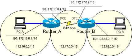
※このページで解説している内容は、Packet Tracer が IGRP に対応していないため、検証することができません。実機における検証結果を紹介しています。検証に使った実機は、古い機種です。
IGRPとRIPの混在時
IGRP と RIP の設定の両方を行った場合、IGRP で選出されたルート、RIPで選出されたルートのどちらが優先されるかを検証します。

まずは、RIPで構成します。
●Router_Aの設定
!
version 11.1
service udp-small-servers
service tcp-small-servers
!
hostname Router_A
!
enable password cisco
!
interface Ethernet0
 ip address 172.16.0.1 255.255.0.0
!
interface Serial0
 ip address 172.17.0.1 255.255.0.0
 clockrate 64000
!
router rip
 network 172.16.0.0
 network 172.17.0.0
!
ip classless
!
line con 0
line aux 0
line vty 0 4
 password cisco
 login
!
end
●Router_Bの設定
!
version 11.1
service udp-small-servers
service tcp-small-servers
!
hostname Router_B
!
enable password cisco
!
interface Ethernet0
 ip address 172.18.0.1 255.255.0.0
!
interface Serial0
 ip address 172.17.0.2 255.255.0.0
 no fair-queue
!
router rip
 network 172.17.0.0
 network 172.18.0.0
!
ip classless
logging buffered
!
line con 0
 exec-timeout 0 0
line aux 0
line vty 0 4
 password cisco
 login
!
end
Router_A、Router_Bのルーティングテーブルを確認してみます。
RIPでネットワークを構築したので、もちろん、それぞれのルータでRIPのルートが登録されています。
●Router_Aのルーティングテーブル
Gateway of last resort is not set

C    172.16.0.0/16 is directly connected, Ethernet0
C    172.17.0.0/16 is directly connected, Serial0
R    172.18.0.0/16 [120/1] via 172.17.0.2, 00:00:02, Serial0
●Router_Bのルーティングテーブル
Gateway of last resort is not set

R    172.16.0.0/16 [120/1] via 172.17.0.1, 00:00:24, Serial0
C    172.17.0.0/16 is directly connected, Serial0
C    172.18.0.0/16 is directly connected, Ethernet0
このRIPの設定に、IGRPの設定を加えます。
Router_Aで、IGRPの設定を追加します。
Router(config)#router igrp 1
Router(config-router)#network 172.16.0.0
Router(config-router)#network 172.17.0.0
Router_Bでは、IGRPの設定を追加します。
Router(config)#router igrp 1
Router(config-router)#network 172.17.0.0
Router(config-router)#network 172.18.0.0
と設定します。
●Router_Aの設定
!
version 11.1
service udp-small-servers
service tcp-small-servers
!
hostname Router_A
!
enable password cisco
!
interface Ethernet0
 ip address 172.16.0.1 255.255.0.0
!
interface Serial0
 ip address 172.17.0.1 255.255.0.0
 clockrate 64000
!
router rip
 network 172.16.0.0
 network 172.17.0.0
!
router igrp 1
 network 172.16.0.0
 network 172.17.0.0
!
ip classless
!
line con 0
line aux 0
line vty 0 4
 password cisco
 login
!
end
●Router_Bの設定
!
version 11.1
service udp-small-servers
service tcp-small-servers
!
hostname Router_B
!
enable password cisco
!
interface Ethernet0
 ip address 172.18.0.1 255.255.0.0
!
interface Serial0
 ip address 172.17.0.2 255.255.0.0
 no fair-queue
!
router rip
 network 172.17.0.0
 network 172.18.0.0
!
router igrp 1
 network 172.17.0.0
 network 172.18.0.0
!
ip classless
logging buffered
!
line con 0
 exec-timeout 0 0
line aux 0
line vty 0 4
 password cisco
 login
!
end
設定が完了したら、「show ip route」コマンドで、ルーティングテーブルを確認してみましょう!
●Router_Aのルーティングテーブル
Gateway of last resort is not set

C    172.16.0.0/16 is directly connected, Ethernet0
C    172.17.0.0/16 is directly connected, Serial0
I    172.18.0.0/16 [100/8576] via 172.17.0.2, 00:00:11, Serial0
●Router_Bのルーティングテーブル
Gateway of last resort is not set

I    172.16.0.0/16 [100/8576] via 172.17.0.1, 00:00:17, Serial0
C    172.17.0.0/16 is directly connected, Serial0
C    172.18.0.0/16 is directly connected, Ethernet0
先ほどの RIP のルートが消え、IGRP のルートに上書きされていることが分かります。
それでは、Ciscoルータは、何を基準にしてルーティングテーブルに登録する経路を決めているのでしょうか?
それは、アドミニストレーティブディスタンス(Administrative Distance)という値が関係してきます。アドミニストレーティブディスタンス値は、下の表のように定義されています。
| 経路情報 | アドミニストレーティブディスタンス値 |
| 直接接続のルート | 0 |
| スタティックルート | 1 |
| EIGRPサマリ | 5 |
| 外部BGP | 20 |
| EIGRP内部ルート | 90 |
| IGRP | 100 |
| OSPF | 110 |
| IS-IS | 115 |
| RIP | 120 |
| EGP | 140 |
| EIGRP外部ルート | 170 |
| 内部BGP | 200 |
| 不明(Unkown) | 255 |
ルーティングプロトコルで学習した経路は、アドミニストレーティブディスタンス値の小さい方を信頼性が高いと判断して、ルーティングテーブルに登録します。
ルータにRIP、IGRPの両方の設定を行った場合だと
RIP ・・・ 120
IGRP ・・・ 100
になります。
従って
アドミニストレーティブディスタンスの値が小さい IGRP によって学習された経路がルーティングテーブルに登録されるようになるのです。
次の「IGRP(不等コストロードバランシング)」では、IGRPの不等ロードバランシングについて解説します。
