このページで解説している内容は、以下の YouTube 動画の解説で見ることができます。
演習ファイルのダウンロード
ネットワークの構成を Packet Tracer で一から設定していくのは大変かと思います。「ダウンロード」から演習で使用するファイルのダウンロードができます。ファイルは、McAfee インターネットセキュリティでウイルスチェックをしておりますが、ダウンロードは自己責任でお願いいたします。
BGPシナリオ演習2(経路流入による過負荷を防ぐ)
ここでは、「BGPシナリオ演習1(経路流入による過負荷を防ぐ)」で構築したBGPネットワークを検証していきます。
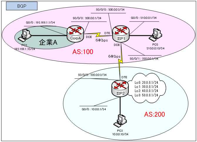
ネットワークの構成は、下図のとおりです。

BGPテーブルの確認
ISP1、ISP2のBGPテーブルを確認します。
●ISP1のBGPテーブル
ISP1#show ip bgp
BGP table version is 9, local router ID is 220.0.0.1
Status codes: s suppressed, d damped, h history, * valid, > best, i - internal,
              r RIB-failure, S Stale
Origin codes: i - IGP, e - EGP, ? - incomplete

   Network          Next Hop            Metric LocPrf Weight Path
*> 10.0.0.0/24       220.0.0.2                0     0     0 200 i
*> 20.0.0.0/24       220.0.0.2                0     0     0 200 i
*> 30.0.0.0/24       220.0.0.2                0     0     0 200 i
*> 40.0.0.0/24       220.0.0.2                0     0     0 200 i
*> 50.0.0.0/24       220.0.0.2                0     0     0 200 i
*> 192.168.1.0/24    0.0.0.0                  0     0     0 100 i
*> 200.0.0.0/24      0.0.0.0                  0     0 32768 i
*> 210.0.0.0/24      0.0.0.0                  0     0 32768 i
●ISP2のBGPテーブル
ISP2#show ip bgp
BGP table version is 9, local router ID is 50.0.0.1
Status codes: s suppressed, d damped, h history, * valid, > best, i - internal,
              r RIB-failure, S Stale
Origin codes: i - IGP, e - EGP, ? - incomplete

   Network          Next Hop            Metric LocPrf Weight Path
*> 10.0.0.0/24       0.0.0.0                  0     0 32768 i
*> 20.0.0.0/24       0.0.0.0                  0     0 32768 i
*> 30.0.0.0/24       0.0.0.0                  0     0 32768 i
*> 40.0.0.0/24       0.0.0.0                  0     0 32768 i
*> 50.0.0.0/24       0.0.0.0                  0     0 32768 i
*> 192.168.1.0/24    220.0.0.1                0     0     0 100 i
*> 200.0.0.0/24      220.0.0.1                0     0     0 100 i
*> 210.0.0.0/24      220.0.0.1                0     0     0 100 i
ルーティングテーブルの確認
各ルータのルーティングテーブルを確認してみます。
●CorpAのルーティングテーブル
CorpA#show ip route
Codes: L - local, C - connected, S - static, R - RIP, M - mobile, B - BGP
       D - EIGRP, EX - EIGRP external, O - OSPF, IA - OSPF inter area
       N1 - OSPF NSSA external type 1, N2 - OSPF NSSA external type 2
       E1 - OSPF external type 1, E2 - OSPF external type 2, E - EGP
       i - IS-IS, L1 - IS-IS level-1, L2 - IS-IS level-2, ia - IS-IS inter area
       * - candidate default, U - per-user static route, o - ODR
       P - periodic downloaded static route

Gateway of last resort is 200.0.0.2 to network 0.0.0.0

     192.168.1.0/24 is variably subnetted, 2 subnets, 2 masks
C       192.168.1.0/24 is directly connected, GigabitEthernet0/0
L       192.168.1.1/32 is directly connected, GigabitEthernet0/0
     200.0.0.0/24 is variably subnetted, 2 subnets, 2 masks
C       200.0.0.0/24 is directly connected, Serial0/0/0
L       200.0.0.1/32 is directly connected, Serial0/0/0
S*   0.0.0.0/0 [1/0] via 200.0.0.2
●ISP1のルーティングテーブル
ISP1#show ip route
Codes: L - local, C - connected, S - static, R - RIP, M - mobile, B - BGP
       D - EIGRP, EX - EIGRP external, O - OSPF, IA - OSPF inter area
       N1 - OSPF NSSA external type 1, N2 - OSPF NSSA external type 2
       E1 - OSPF external type 1, E2 - OSPF external type 2, E - EGP
       i - IS-IS, L1 - IS-IS level-1, L2 - IS-IS level-2, ia - IS-IS inter area
       * - candidate default, U - per-user static route, o - ODR
       P - periodic downloaded static route

Gateway of last resort is not set

     10.0.0.0/24 is subnetted, 1 subnets
B       10.0.0.0/24 [20/0] via 220.0.0.2, 00:00:00
     20.0.0.0/24 is subnetted, 1 subnets
B       20.0.0.0/24 [20/0] via 220.0.0.2, 00:00:00
     30.0.0.0/24 is subnetted, 1 subnets
B       30.0.0.0/24 [20/0] via 220.0.0.2, 00:00:00
     40.0.0.0/24 is subnetted, 1 subnets
B       40.0.0.0/24 [20/0] via 220.0.0.2, 00:00:00
     50.0.0.0/24 is subnetted, 1 subnets
B       50.0.0.0/24 [20/0] via 220.0.0.2, 00:00:00
S    192.168.1.0/24 [1/0] via 200.0.0.1
     200.0.0.0/24 is variably subnetted, 2 subnets, 2 masks
C       200.0.0.0/24 is directly connected, Serial0/0/0
L       200.0.0.2/32 is directly connected, Serial0/0/0
     210.0.0.0/24 is variably subnetted, 2 subnets, 2 masks
C       210.0.0.0/24 is directly connected, GigabitEthernet0/0
L       210.0.0.1/32 is directly connected, GigabitEthernet0/0
     220.0.0.0/24 is variably subnetted, 2 subnets, 2 masks
C       220.0.0.0/24 is directly connected, Serial0/0/1
L       220.0.0.1/32 is directly connected, Serial0/0/1
●ISP2のルーティングテーブル
ISP2#show ip route
Codes: L - local, C - connected, S - static, R - RIP, M - mobile, B - BGP
       D - EIGRP, EX - EIGRP external, O - OSPF, IA - OSPF inter area
       N1 - OSPF NSSA external type 1, N2 - OSPF NSSA external type 2
       E1 - OSPF external type 1, E2 - OSPF external type 2, E - EGP
       i - IS-IS, L1 - IS-IS level-1, L2 - IS-IS level-2, ia - IS-IS inter area
       * - candidate default, U - per-user static route, o - ODR
       P - periodic downloaded static route

Gateway of last resort is not set

     10.0.0.0/8 is variably subnetted, 2 subnets, 2 masks
C       10.0.0.0/24 is directly connected, GigabitEthernet0/0
L       10.0.0.1/32 is directly connected, GigabitEthernet0/0
     20.0.0.0/8 is variably subnetted, 2 subnets, 2 masks
C       20.0.0.0/24 is directly connected, Loopback0
L       20.0.0.1/32 is directly connected, Loopback0
     30.0.0.0/8 is variably subnetted, 2 subnets, 2 masks
C       30.0.0.0/24 is directly connected, Loopback1
L       30.0.0.1/32 is directly connected, Loopback1
     40.0.0.0/8 is variably subnetted, 2 subnets, 2 masks
C       40.0.0.0/24 is directly connected, Loopback2
L       40.0.0.1/32 is directly connected, Loopback2
     50.0.0.0/8 is variably subnetted, 2 subnets, 2 masks
C       50.0.0.0/24 is directly connected, Loopback3
L       50.0.0.1/32 is directly connected, Loopback3
B    192.168.1.0/24 [20/0] via 220.0.0.1, 00:00:00
B    200.0.0.0/24 [20/0] via 220.0.0.1, 00:00:00
B    210.0.0.0/24 [20/0] via 220.0.0.1, 00:00:00
     220.0.0.0/24 is variably subnetted, 2 subnets, 2 masks
C       220.0.0.0/24 is directly connected, Serial0/0/0
L       220.0.0.2/32 is directly connected, Serial0/0/0
ここで、もう一度、設定したことを確認してみます。
・CorpAには、ISP1へのデフォルトルートがある。
・ISP1には、BGPルート「10.0.0.0/24」「20.0.0.0/24」「30.0.0.0/24」「40.0.0.0/24」「50.0.0.0/24」のルートがある。
・ISP2には、BGPルート「192.168.1.0/24」「200.0.0.0/24」「210.0.0.0/24」のルートがある。
Pingによる疎通確認
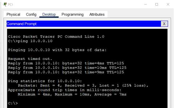
PC1から ping を行います。どこを宛先としてもよいのですが、ここでは、PC3へ ping を行ってみます。
C:>ping 10.0.0.10
●PC1からPC3への ping

このように、ISP1 が、ISP2 から学習した経路情報を顧客である企業AのCorpAルータにアドバタイズしないようにすることで、CorpAルータにインターネットからの大量の経路情報の流入を防ぎ、過負荷状態になることを避けることができます。
