IS-IS(設定)
ここでは、IS-ISを使用してネットワークを構築していきます。
ここでは、Cisco1710、EnterpriseフィーチャーセットIOSの組み合わせで動作確認をしております。
※IS-ISを実行するには、IOSがCLNSをサポートしている必要があります。EnterpriseフィーチャーセットのIOSが必要です。
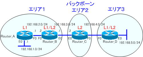
使用するネットワークは、下図になります

IS-ISの設定では、ルータのIS-ISを有効にしてNETを割り当てる必要があります。

●NETの割り当て
各ルータのNETの割り当ては、以下のように割り当てます。
Router_A ・・・ 01.0000.0000.0001.00
Router_B ・・・ 01.0000.0000.0002.00
Router_C ・・・ 02.0000.0000.0003.00
Router_D ・・・ 03.0000.0000.0004.00
Router_Aの設定を例にIS-ISの設定を紹介します。
●Router_Aの設定
Router_A(config)router isis
Router_A(config-router)#net 01.0000.0000.0001.00
L1ルータであるか、L2ルータであるかを指定します。Router_Aは、L1ルータであれば以下のように設定します。
Router_A(config-router)#is-type level-1
L1ルータ、L1/L2ルータ、L2ルータの指定は、以下のように指定します。
L1ルータ ・・・ is-type level-1
L1/L2ルータ ・・・ is-type level-1-2
L2ルータ ・・・ is-type level-2-only
※デフォルトでL1/L2ルータである場合があります。
●インターフェイスの設定
RIP、IGRP、OSPFなどのルーティングプロトコルとは、違い、インターフェイスの設定も必要です。インターフェイスでIS-ISを有効にする必要があります。
Router_A(config)int e0
Router_A(config-if)#ip router isis
Router_A(config-if)#exit
Router_A(config)int f0
Router_A(config-if)#ip router isis
それでは、各ルータを設定してゆきましょう。各ルータの設定は、以下のようになります。
強制的にインターフェイスをUPさせるために、Router_A、Router_DのE0インターフェイスで「no keepalive」コマンドを設定しておきます。
●Router_Aの設定
!
version 12.4
service timestamps debug datetime msec
service timestamps log datetime msec
no service password-encryption
!
hostname Router_A
!
boot-start-marker
boot-end-marker
!
enable password cisco
!
no aaa new-model
memory-size iomem 25
!
ip cef
!
interface Ethernet0
 ip address 192.168.1.1 255.255.255.0
 ip router isis
 half-duplex
 no keepalive
!
interface FastEthernet0
 ip address 192.168.2.1 255.255.255.0
 ip router isis
 speed auto
!
router isis
 net 01.0000.0000.0001.00
 is-type level-1
!
ip forward-protocol nd
no ip http server
no ip http secure-server
!
control-plane
!
line con 0
line aux 0
line vty 0 4
 password cisco
 login
!
end
●Router_Bの設定
!
version 12.4
service timestamps debug datetime msec
service timestamps log datetime msec
no service password-encryption
!
hostname Router_B
!
boot-start-marker
boot-end-marker
!
enable password cisco
!
no aaa new-model
memory-size iomem 25
!
ip cef
!
interface Ethernet0
 ip address 192.168.3.1 255.255.255.0
 ip router isis
 half-duplex
!
interface FastEthernet0
 ip address 192.168.2.2 255.255.255.0
 ip router isis
 speed auto
!
router isis
 net 01.0000.0000.0002.00
!
ip forward-protocol nd
no ip http server
no ip http secure-server
!
control-plane
!
line con 0
line aux 0
line vty 0 4
 password cisco
 login
!
end
●Router_Cの設定
!
version 12.4
service timestamps debug datetime msec
service timestamps log datetime msec
no service password-encryption
!
hostname Router_C
!
boot-start-marker
boot-end-marker
!
enable password cisco
!
no aaa new-model
memory-size iomem 25
!
ip cef
!
interface Ethernet0
 ip address 192.168.3.2 255.255.255.0
 ip router isis
 half-duplex
!
interface FastEthernet0
 ip address 192.168.4.1 255.255.255.0
 ip router isis
 speed auto
!
router isis
 net 02.0000.0000.0003.00
 is-type level-2-only
!
ip forward-protocol nd
no ip http server
no ip http secure-server
!
control-plane
!
line con 0
line aux 0
line vty 0 4
 password cisco
 login
!
end
●Router_Dの設定
!
version 12.4
service timestamps debug datetime msec
service timestamps log datetime msec
no service password-encryption
!
hostname Router_D
!
boot-start-marker
boot-end-marker
!
enable password cisco
!
no aaa new-model
memory-size iomem 25
!
ip cef
!
interface Ethernet0
 ip address 192.168.5.1 255.255.255.0
 ip router isis
 half-duplex
 no keepalive
!
interface FastEthernet0
 ip address 192.168.4.2 255.255.255.0
 ip router isis
 speed auto
!
router isis
 net 03.0000.0000.0004.00
!
ip forward-protocol nd
no ip http server
no ip http secure-server
!
control-plane
!
line con 0
line aux 0
line vty 0 4
 password cisco
 login
!
end
ルーティングテーブルの確認
ルーティングテーブルを確認してみます。
Router_Aのルーティングテーブルを確認してみます。
●Router_Aのルーティングテーブル
Gateway of last resort is 192.168.2.2 to network 0.0.0.0

C    192.168.1.0/24 is directly connected, Ethernet0
C    192.168.2.0/24 is directly connected, FastEthernet0
i L1 192.168.3.0/24 [115/20] via 192.168.2.2, FastEthernet0
i*L1 0.0.0.0/0 [115/10] via 192.168.2.2, FastEthernet0
「i L1」からレベル1ISISの経路を2つ学習していることが分かります。
「i L2」の経路がありません。「i L2」の経路に「0.0.0.0」があります。これは、デフォルトルートです。エリア外のルートはデフォルトルートになります。
これは、OSPFのスタブエリアとよく似ています。Router_B(L1/L2ルータ)は、エリア外のルートをデフォルトルートとしてアドバタイズしているのです。
Router_Bのルーティングテーブルを確認してみます。
●Router_Bのルーティングテーブル
Gateway of last resort is not set

i L2 192.168.4.0/24 [115/20] via 192.168.3.2, Ethernet0
i L2 192.168.5.0/24 [115/30] via 192.168.3.2, Ethernet0
i L1 192.168.1.0/24 [115/20] via 192.168.2.1, FastEthernet0
C    192.168.2.0/24 is directly connected, FastEthernet0
C    192.168.3.0/24 is directly connected, Ethernet0
「i L1」からレベル1のISISの経路、「i L2」から、レベル2のISISの経路があることを確認できます。
Router_Cのルーティングテーブルを確認してみます。
●Router_Cのルーティングテーブル
Gateway of last resort is not set

C    192.168.4.0/24 is directly connected, FastEthernet0
i L2 192.168.5.0/24 [115/20] via 192.168.4.2, FastEthernet0
i L2 192.168.1.0/24 [115/30] via 192.168.3.1, Ethernet0
i L2 192.168.2.0/24 [115/20] via 192.168.3.1, Ethernet0
C    192.168.3.0/24 is directly connected, Ethernet0
「i L2」から、レベル2のISISの経路があることを確認できます。
Router_Dのルーティングテーブルを確認してみます。
●Router_Dのルーティングテーブル
Gateway of last resort is not set

C    192.168.4.0/24 is directly connected, FastEthernet0
C    192.168.5.0/24 is directly connected, Ethernet0
i L2 192.168.1.0/24 [115/40] via 192.168.4.1, FastEthernet0
i L2 192.168.2.0/24 [115/30] via 192.168.4.1, FastEthernet0
i L2 192.168.3.0/24 [115/20] via 192.168.4.1, FastEthernet0
「i L2」からレベル2のISISの経路があることが確認できます。
次の「IS-IS(確認コマンド)」では、IS-ISの確認コマンドを解説します。
