ルート再配送(IGRPとEIGRP)
Packet Tracer では、IGRP がサポートされていないため、ここでは、実機における設定例を紹介します。
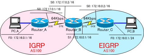
下の図のIGRP、EIGRPで構成されたネットワーク間で通信できるようにします。
実機確認においては、Cisco1720とCisco1721を使用しております。
異なるルーティングプロトコル間で経路情報を共有するには、再配送の設定が必要になります。その設定は、少々難しいのですが、EIGRPとIGRP間では、再配布は自動的に行われます。
IGRP、EIGRPでは、経路を計算するメトリックとして、「帯域幅」「遅延」「負荷」「信頼性」「MTU」の5つが使われます。
メトリックの計算式は、以下になります。
メトリック=[K1×帯域幅 + (K2 × 帯域幅) ÷ (256 - 負荷) + (K3 × 遅延)] × [K5 ÷ (信頼度 + K4)]
係数であるK1~K5のデフォルト値は
K1=1,K2=0,K3=1,K4=0,K5=0
になっているので
メトリック = 帯域幅 + 遅延
K4=0,K5=0の場合、[K5 ÷ (信頼度 + K4)]は、計算されないようになっています。
EIGRPでは、帯域幅と遅延がIGRPの256倍の値が使われます。
EIGRPの帯域幅 = (10,000,000 ÷ 帯域幅) × 256
EIGRPの遅延 = (遅延 ÷ 10) × 256
計算式から分かるように、EIGRPとIGRPのメトリックは、256で乗除すれば、簡単にIGRP、EIGRPのメトリックに変換できそうなことが分かります。
IGRP、EIGRPは、シスコ独自のプロトコルで相性がよく、AS番号が一致していれば、自動的に、ルートを再配送してくれるようになっています。
それでは、下の図のようにネットワークを構成し、ネットワークを構築していきます。

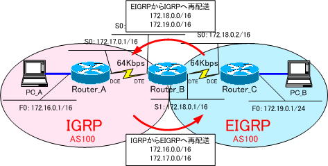
通常、再配送の設定では、境界に位置するルータで、下の図のように
・IGRPからEIGRPへの再配送
・EIGRPからIGRPへの再配送
の設定が必要になってくるのですが、この再配送の設定が不要になります。
各ルータでルーティングの設定を行うだけで、自動的に再配送するようになります。

Router_A、Router_CのF0にPCを接続するのは、少々面倒です。
強制的にインターフェイスをUPさせるために、F0インターフェイスで「no keepalive」コマンドを設定しておきます。
●Router_Aの設定
!
version 12.2
service timestamps debug uptime
service timestamps log uptime
no service password-encryption
!
hostname Router_A
!
enable password cisco
!
memory-size iomem 25
ip subnet-zero
!
interface FastEthernet0
 ip address 172.16.0.1 255.255.0.0
 no keepalive
 speed auto
!
interface Serial0
 bandwidth 64
 ip address 172.17.0.1 255.255.0.0
 no fair-queue
 clockrate 64000
!
interface Serial1
 no ip address
 shutdown
!
interface Serial2
 no ip address
 shutdown
!
router igrp 100
 network 172.16.0.0
 network 172.17.0.0
!
ip classless
no ip http server
!
line con 0
line aux 0
line vty 0 4
 password cisco
 login
!
end
●Router_Bの設定
!
version 12.1
service timestamps debug uptime
service timestamps log uptime
no service password-encryption
!
hostname Router_B
!
logging buffered 4096 debugging
enable password cisco
!
memory-size iomem 25
ip subnet-zero
!
interface Serial0
 bandwidth 64
 ip address 172.17.0.2 255.255.0.0
 no fair-queue
!
interface Serial1
 bandwidth 64
 ip address 172.18.0.1 255.255.0.0
!
interface FastEthernet0
 no ip address
 shutdown
 speed auto
!
router eigrp 100
 network 172.18.0.0
!
router igrp 100
 network 172.17.0.0
!
ip classless
no ip http server
!
line con 0
 exec-timeout 0 0
 transport input none
line aux 0
line vty 0 4
 password cisco
 login
!
end
●Router_Cの設定
!
version 12.3
service timestamps debug datetime msec
service timestamps log datetime msec
no service password-encryption
!
hostname Router_C
!
boot-start-marker
boot-end-marker
!
enable password cisco
!
no aaa new-model
ip subnet-zero
!
ip cef
!
interface FastEthernet0
 ip address 172.19.0.1 255.255.0.0
 speed auto
 no keepalive
!
interface Serial0
 bandwidth 64
 ip address 172.18.0.2 255.255.0.0
 clockrate 64000
 no fair-queue
!
router eigrp 100
 network 172.18.0.0
 network 172.19.0.0
 auto-summary
!
ip classless
no ip http server
!
!
line con 0
line aux 0
line vty 0 4
 password cisco
 login
!
end
各ルータのルーティングテーブルを確認してみましょう!
●Router_Aのルーティングテーブル
Gateway of last resort is not set

C    172.17.0.0/16 is directly connected, Serial0
C    172.16.0.0/16 is directly connected, FastEthernet0
I    172.19.0.0/16 [100/160260] via 172.17.0.2, 00:00:26, Serial0
I    172.18.0.0/16 [100/160250] via 172.17.0.2, 00:00:26, Serial0
IGRPでは、内部ルートと外部ルートの区別が行われません。EIGRPよる外部ルートを識別できず相変わらず、IGRPで学習したものとして扱っていることが分かります。
●Router_Bのルーティングテーブル
Gateway of last resort is not set

C    172.17.0.0/16 is directly connected, Serial0
I    172.16.0.0/16 [100/158260] via 172.17.0.1, 00:00:50, Serial0
D    172.19.0.0/16 [90/40514560] via 172.18.0.2, 00:02:53, Serial1
C    172.18.0.0/16 is directly connected, Serial1
●Router_Cのルーティングテーブル
Gateway of last resort is not set

D EX 172.17.0.0/16 [170/41024000] via 172.18.0.1, 00:03:18, Serial0
D EX 172.16.0.0/16 [170/41026560] via 172.18.0.1, 00:03:18, Serial0
C    172.19.0.0/16 is directly connected, FastEthernet0
C    172.18.0.0/16 is directly connected, Serial0
EIGRPでは、IGRPや外部から学習したルートに外部(EXTERNAL)とタグ付けを行って、EIGRPのルートと識別します。IGRPから再配送されたルートを外部ルートとして識別しています。
