OSPF(DR・BDR_その4)
の続きです。
DR、BDRの選出
DR、BDRの選出がどのように行われたかを確認してみましょう。「OSPF(その1)」でも触れましたが、DR、BDRの選出には、ROUTERIDと優先度が関係してきます。
DR、BDRの選出のされ方のおさらいです。
<DRの選出ルール>
1.優先度が一番大きいものから、DR、BDRの順に選出される。
PRIORITY=0~255で、数値が大きいほど優先度が高くなります。値が0の場合はDRに選出されません。
2.優先度が同じときは、ROUTERIDが大きいものから、DR、BDRの順に選出される。
IPアドレスの番号が、高いほど優先度が高くなります。例えば、「192.168.1.1」より、「192.168.1.2」の方が優先度が高いことになります。また、ROUTERIDは、自身の装置のインターフェイスに振られたIPアドレスの中で最も大きなものが選択されます。
※アクティブなIPアドレスの中で最も値が大きいものが選択されます。
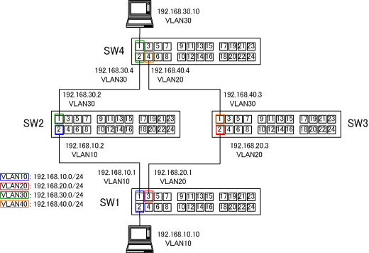
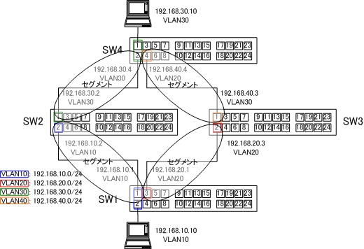
OSPFネットワークの構成は、下の図の通りです。

イーサネットなのでセグメント内で、1台ずつDR、BDRが選出されます。

「SHOW OSPF INTERFACE」コマンドを使って、DR、BDRを確認していきます。
●SW1側
Manager > show ospf interface
                                              Designated rtr   Backup DR
Iface    Status    Area             State     / Virtual nbr    / Transit area
-------------------------------------------------------------------------------
vlan10   Enabled   Backbone         backupDR  192.168.10.2     192.168.10.1
vlan20   Enabled   Backbone         backupDR  192.168.20.3     192.168.20.1
-------------------------------------------------------------------------------
●SW2側
Manager > show ospf interface
                                              Designated rtr   Backup DR
Iface    Status    Area             State     / Virtual nbr    / Transit area
-------------------------------------------------------------------------------
vlan10   Enabled   Backbone         DR        192.168.10.2     192.168.10.1
vlan30   Enabled   Backbone         backupDR  192.168.30.4     192.168.30.2
-------------------------------------------------------------------------------
●SW3側
Manager > show ospf interface
                                              Designated rtr   Backup DR
Iface    Status    Area             State     / Virtual nbr    / Transit area
-------------------------------------------------------------------------------
vlan20   Enabled   Backbone         DR        192.168.20.3     192.168.20.1
vlan40   Enabled   Backbone         backupDR  192.168.40.4     192.168.40.3
-------------------------------------------------------------------------------
●SW4側
Manager > show ospf interface
                                              Designated rtr   Backup DR
Iface    Status    Area             State     / Virtual nbr    / Transit area
-------------------------------------------------------------------------------
vlan30   Enabled   Backbone         DR        192.168.30.4     192.168.30.2
vlan40   Enabled   Backbone         DR        192.168.40.4     192.168.40.3
-------------------------------------------------------------------------------
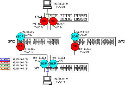
DR、BDRは、以下のようになっているはずです。OSPFは、先にDR、BDRが決まってしまうと、DR,BDRがダウンするまで、変更されることはありません。他のルータ(スイッチ)が追加されたとしても、追加したルータ(スイッチ)が、DR、BDRにならないので、注意してください。
期待通りに、DR、BDRにさせるには、ルータ(スイッチ)を同時に電源を入れる必要があります。

それでは、なぜ、DR、BDRの選出が上の図のようになったのか考えてみましょう!
各スイッチの「ROUTER ID」がどうなっているか確認してみましょう!
「ROUTER ID」を確認するには、「SHOW OSPF」コマンドを使います。
●SW1側
Manager > show ospf
Router ID ....................... 192.168.20.1
OSPF module status .............. Enabled
Area border router status ....... No
AS border router status ......... Disabled
PTP stub network generation ..... Enabled
External LSA count .............. 0
External LSA sum of checksums ... 0
New LSAs originated ............. 4
New LSAs received ............... 13
RIP ............................. None
Dynamic interface support ....... None
Number of active areas .......... 1
Logging ......................... Disabled
Debugging ....................... Disabled
AS external default route:
Status ........................ Disabled
Type .......................... 1
Metric ........................ 1
OSPF thread debugging
Total thread entries ... 10884
Packet entries ......... 243
Timer entries .......... 10641
Command busy entries ... 0
Highest timer tick ..... 1
Timer LSA timestamping
N ......... 1064
Sum ....... 8760
Num LSAs .. 8
Lo ........ 0
Hi ........ 11
SPF timestamping
N ......... 7
Sum ....... 1464
Lo ........ 22
Hi ........ 370
●SW2側
Manager > show ospf

Router ID ....................... 192.168.30.2
OSPF module status .............. Enabled
Area border router status ....... No
AS border router status ......... Disabled
PTP stub network generation ..... Enabled
External LSA count .............. 0
External LSA sum of checksums ... 0
New LSAs originated ............. 7
New LSAs received ............... 11
RIP ............................. None
Dynamic interface support ....... None
Number of active areas .......... 1
Logging ......................... Disabled
Debugging ....................... Disabled
AS external default route:
  Status ........................ Disabled
  Type .......................... 1
  Metric ........................ 1

OSPF thread debugging

  Total thread entries ... 11267
  Packet entries ......... 249
  Timer entries .......... 11018
  Command busy entries ... 0
  Highest timer tick ..... 1

Timer LSA timestamping
  N ......... 1101
  Sum ....... 8833
  Num LSAs .. 8
  Lo ........ 0
  Hi ........ 18

SPF timestamping
  N ......... 7
  Sum ....... 1593
  Lo ........ 23
  Hi ........ 396
●SW3側
Manager > show ospf

Router ID ....................... 192.168.40.3
OSPF module status .............. Enabled
Area border router status ....... No
AS border router status ......... Disabled
PTP stub network generation ..... Enabled
External LSA count .............. 0
External LSA sum of checksums ... 0
New LSAs originated ............. 6
New LSAs received ............... 12
RIP ............................. None
Dynamic interface support ....... None
Number of active areas .......... 1
Logging ......................... Disabled
Debugging ....................... Disabled
AS external default route:
  Status ........................ Disabled
  Type .......................... 1
  Metric ........................ 1

OSPF thread debugging

  Total thread entries ... 11645
  Packet entries ......... 257
  Timer entries .......... 11388
  Command busy entries ... 0
  Highest timer tick ..... 1

Timer LSA timestamping
  N ......... 1138
  Sum ....... 9405
  Num LSAs .. 8
  Lo ........ 0
  Hi ........ 11

SPF timestamping
  N ......... 7
  Sum ....... 1458
  Lo ........ 21
  Hi ........ 357
●SW4側
Manager > show ospf

Router ID ....................... 192.168.40.4
OSPF module status .............. Enabled
Area border router status ....... No
AS border router status ......... Disabled
PTP stub network generation ..... Enabled
External LSA count .............. 0
External LSA sum of checksums ... 0
New LSAs originated ............. 8
New LSAs received ............... 10
RIP ............................. None
Dynamic interface support ....... None
Number of active areas .......... 1
Logging ......................... Disabled
Debugging ....................... Disabled
AS external default route:
  Status ........................ Disabled
  Type .......................... 1
  Metric ........................ 1

OSPF thread debugging

  Total thread entries ... 11940
  Packet entries ......... 265
  Timer entries .......... 11675
  Command busy entries ... 0
  Highest timer tick ..... 1

Timer LSA timestamping
  N ......... 1167
  Sum ....... 9387
  Num LSAs .. 8
  Lo ........ 0
  Hi ........ 19

SPF timestamping
  N ......... 7
  Sum ....... 1637
  Lo ........ 23
  Hi ........ 486
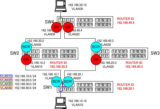
ルータIDを確認すると、下の図のようになっています。
「ROUTER ID」を指定しない場合、各スイッチ(ルータ)において「ROUTER ID」は、アクティブになっているインターフェイスに振られているIPアドレスの中で、もっとも大きなIPアドレスが、「ROUTER ID」になります。
DRは、各セグメントにおいて、最も大きな「ROUTER ID」を持つスイッチ(ルータ)がDRになります。

各セグメントにおいて、「ROUTER ID」の大きい方が、DRに選出されているのが、わかると思います。
ここでは、「ROUTER ID」が、DR、BDRの選出にどのように関与してくるかを確認しました。
次は、「優先度」がどのようにDR、BDRの選出にどのように関与してくるかを確認してみます。
続きは、次の「OSPF(優先度によるDR・BDR_その5)」で紹介しています。
