OSPF(シングルエリア検証その3)
の続きです。
障害時の迂回
ここでは、経路上で障害があった場合に、ちゃんと経路が切り替わるか試してみます。
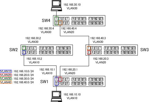
OSPFネットワークの構成は、下の図の通りです。

ルーティングテーブルを確認します。
●SW1側
Manager > show ip route

IP Routes
-------------------------------------------------------------------------------
Destination       Mask              NextHop             Interface           Age
DLCI/Circ.        Type     Policy   Protocol            Metrics      Preference
-------------------------------------------------------------------------------
192.168.10.0      255.255.255.0     0.0.0.0             vlan10             1379
-                 direct   0        interface           1                     0
192.168.10.0      255.255.255.0     0.0.0.0             vlan10             1374
-                 remote   0        ospf-Intra          1                    10
192.168.20.0      255.255.255.0     0.0.0.0             vlan20             1379
-                 direct   0        interface           1                     0
192.168.20.0      255.255.255.0     0.0.0.0             vlan20             1368
-                 remote   0        ospf-Intra          1                    10
192.168.30.0      255.255.255.0     192.168.10.2        vlan10             1330
-                 remote   0        ospf-Intra          2                    10
192.168.40.0      255.255.255.0     192.168.20.3        vlan20             1330
-                 remote   0        ospf-Intra          2                    10
-------------------------------------------------------------------------------
●SW2側
Manager > show ip route

IP Routes
-------------------------------------------------------------------------------
Destination       Mask              NextHop             Interface           Age
DLCI/Circ.        Type     Policy   Protocol            Metrics      Preference
-------------------------------------------------------------------------------
192.168.10.0      255.255.255.0     0.0.0.0             vlan10             1567
-                 direct   0        interface           1                     0
192.168.10.0      255.255.255.0     0.0.0.0             vlan10             1563
-                 remote   0        ospf-Intra          1                    10
192.168.20.0      255.255.255.0     192.168.10.1        vlan10             1518
-                 remote   0        ospf-Intra          2                    10
192.168.30.0      255.255.255.0     0.0.0.0             vlan30             1567
-                 direct   0        interface           1                     0
192.168.30.0      255.255.255.0     0.0.0.0             vlan30             1557
-                 remote   0        ospf-Intra          1                    10
192.168.40.0      255.255.255.0     192.168.30.4        vlan30             1514
-                 remote   0        ospf-Intra          2                    10
-------------------------------------------------------------------------------
●SW3側
Manager > show ip route

IP Routes
-------------------------------------------------------------------------------
Destination       Mask              NextHop             Interface           Age
DLCI/Circ.        Type     Policy   Protocol            Metrics      Preference
-------------------------------------------------------------------------------
192.168.10.0      255.255.255.0     192.168.20.1        vlan20             1552
-                 remote   0        ospf-Intra          2                    10
192.168.20.0      255.255.255.0     0.0.0.0             vlan20             1600
-                 direct   0        interface           1                     0
192.168.20.0      255.255.255.0     0.0.0.0             vlan20             1596
-                 remote   0        ospf-Intra          1                    10
192.168.30.0      255.255.255.0     192.168.40.4        vlan40             1547
-                 remote   0        ospf-Intra          2                    10
192.168.40.0      255.255.255.0     0.0.0.0             vlan40             1600
-                 direct   0        interface           1                     0
192.168.40.0      255.255.255.0     0.0.0.0             vlan40             1590
-                 remote   0        ospf-Intra          1                    10
-------------------------------------------------------------------------------
●SW4側
Manager > show ip route

IP Routes
-------------------------------------------------------------------------------
Destination       Mask              NextHop             Interface           Age
DLCI/Circ.        Type     Policy   Protocol            Metrics      Preference
-------------------------------------------------------------------------------
192.168.10.0      255.255.255.0     192.168.30.2        vlan30             1598
-                 remote   0        ospf-Intra          2                    10
192.168.20.0      255.255.255.0     192.168.40.3        vlan40             1603
-                 remote   0        ospf-Intra          2                    10
192.168.30.0      255.255.255.0     0.0.0.0             vlan30             1655
-                 direct   0        interface           1                     0
192.168.30.0      255.255.255.0     0.0.0.0             vlan30             1651
-                 remote   0        ospf-Intra          1                    10
192.168.40.0      255.255.255.0     0.0.0.0             vlan40             1655
-                 direct   0        interface           1                     0
192.168.40.0      255.255.255.0     0.0.0.0             vlan40             1645
-                 remote   0        ospf-Intra          1                    10
-------------------------------------------------------------------------------
SW1のルーティングテーブルを見ると
192.168.30.0      255.255.255.0     192.168.10.2        vlan10             1330
-                 remote   0        ospf-Intra          2                    10
192.168.10.10の端末から192.168.30.10の端末への経路は、
SW1 → SW2 → SW4
の経路を辿ることが分かります。
そこで、「SW2⇔SW4」間のケーブルを抜き下の図のような構成にします。

するとSW1のルーティングテーブルは、下のように変化します。
●SW1側
Manager > show ip route

IP Routes
-------------------------------------------------------------------------------
Destination       Mask              NextHop             Interface           Age
DLCI/Circ.        Type     Policy   Protocol            Metrics      Preference
-------------------------------------------------------------------------------
192.168.10.0      255.255.255.0     0.0.0.0             vlan10             4141
-                 direct   0        interface           1                     0
192.168.10.0      255.255.255.0     0.0.0.0             vlan10             4136
-                 remote   0        ospf-Intra          1                    10
192.168.20.0      255.255.255.0     0.0.0.0             vlan20             4141
-                 direct   0        interface           1                     0
192.168.20.0      255.255.255.0     0.0.0.0             vlan20             4130
-                 remote   0        ospf-Intra          1                    10
192.168.30.0      255.255.255.0     192.168.20.3        vlan20               41
-                 remote   0        ospf-Intra          3                    10
192.168.40.0      255.255.255.0     192.168.20.3        vlan20             4086
-                 remote   0        ospf-Intra          2                    10
-------------------------------------------------------------------------------
192.168.10.10の端末から192.168.30.10の端末への経路は、
SW1 → SW3 → SW4
に経路が変化します。
OSPF検証コマンド
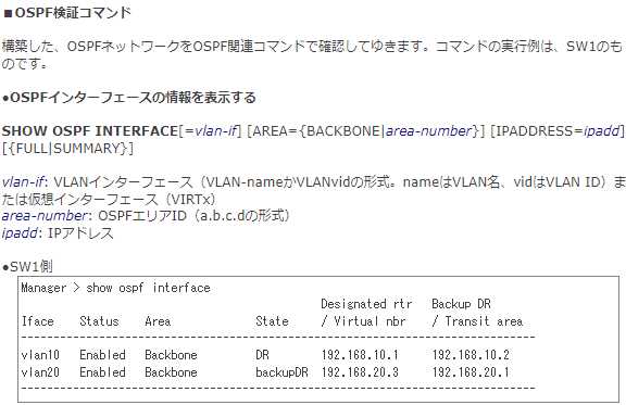
構築した、OSPFネットワークをOSPF関連コマンドで確認してゆきます。コマンドの実行例は、SW1のものです。
●OSPFインターフェイスの情報を表示する
SHOW OSPF INTERFACE[=vlan-if] [AREA={BACKBONE|area-number}] [IPADDRESS=ipadd] [{FULL|SUMMARY}]
vlan-if: VLANインターフェイス(VLAN-nameかVLANvidの形式。nameはVLAN名、vidはVLAN ID)または仮想インターフェイス(VIRTx)
area-number: OSPFエリアID(a.b.c.dの形式)
ipadd: IPアドレス
●SW1側
Manager > show ospf interface
                                              Designated rtr   Backup DR
Iface    Status    Area             State     / Virtual nbr    / Transit area
-------------------------------------------------------------------------------
vlan10   Enabled   Backbone         DR        192.168.10.1     192.168.10.2
vlan20   Enabled   Backbone         backupDR  192.168.20.3     192.168.20.1
-------------------------------------------------------------------------------
●OSPFモジュールのグローバル設定情報を表示する
SHOW OSPF
●SW1側
Manager > show ospf

Router ID ....................... 192.168.20.1
OSPF module status .............. Enabled
Area border router status ....... No
AS border router status ......... Disabled
PTP stub network generation ..... Enabled
External LSA count .............. 0
External LSA sum of checksums ... 0
New LSAs originated ............. 6
New LSAs received ............... 9
RIP ............................. None
Dynamic interface support ....... None
Number of active areas .......... 1
Logging ......................... Disabled
Debugging ....................... Disabled
AS external default route:
  Status ........................ Disabled
  Type .......................... 1
  Metric ........................ 1

OSPF thread debugging

  Total thread entries ... 3676
  Packet entries ......... 95
  Timer entries .......... 3581
  Command busy entries ... 0
  Highest timer tick ..... 1

Timer LSA timestamping
  N ......... 358
  Sum ....... 2759
  Num LSAs .. 8
  Lo ........ 0
  Hi ........ 10

SPF timestamping
  N ......... 4
  Sum ....... 718
  Lo ........ 25
  Hi ........ 360
隣接するOSPFルーターの情報を表示する
SHOW OSPF NEIGHBOUR[=ipadd][INTERFACE=vlan-if]
ipadd: IPアドレス
vlan-if: VLANインターフェイス(VLAN-nameかVLANvidの形式。nameはVLAN名、vidはVLAN ID)または仮想インターフェイス(VIRTx)
CiscoIOSに馴染みのある方は、「neighbour」ってスペルミス!って思われたかもしれません。CiscoIOSでは、「neighbor」ですが、アライドでは、「neighbour」です。注意してください。
●SW1側
Manager > show ospf neighbour

IP address       State     Interface  Router ID        Priority  LSRxmtQ  Type
-------------------------------------------------------------------------------
192.168.10.2     full       vlan10    192.168.10.2         1         0    Dyn
192.168.20.3     full       vlan20    192.168.40.3         1         0    Dyn
-------------------------------------------------------------------------------
OSPF通信ができていない場合、Stateが「full」になっているかどうか、確認しておきましょう!
それでは、図のようなOSPFネットワークが構築できたところで、DR、BDRの選出がどうなったかを確認していきましょう!
続きは、次の「OSPF(DR・BDR_その4)」で紹介しています。
