このページで解説している内容は、以下の YouTube 動画の解説で見ることができます。
演習ファイルのダウンロード
ネットワークの構成を Packet Tracer で一から設定していくのは大変かと思います。「ダウンロード」から演習で使用するファイルのダウンロードができます。ファイルは、McAfeeインターネットセキュリティでウイルスチェックをしておりますが、ダウンロードは自己責任でお願いいたします。
RIPとフローティングスタティック(その1)
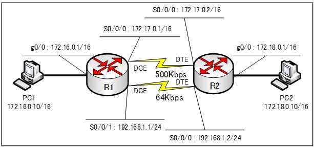
下図のネットワークを、RIPとスタティックルートで構成します。

基本設定
まず、基本設定を行います。ホスト名とIPv4アドレス、RIPv1の設定を行います。
各ルータの基本コンフィグ、下記の通りです。
●基本コンフィグ
●R1のコンフィグ
hostname R1
int g0/0
ip address 172.16.0.1 255.255.0.0
no shutdown
int S0/0/0
ip address 172.17.0.1 255.255.0.0
clock rate 500000
no shutdown
int S0/0/1
ip address 192.168.1.1 255.255.255.0
clock rate 64000
no shutdown
router rip
network 172.16.0.0
network 172.17.0.0
passive-interface g0/0

●R2のコンフィグ
hostname R2
int s0/0/0
ip address 172.17.0.2 255.255.0.0
no shutdown
int s0/0/1
ip address 192.168.1.2 255.255.255.0
no shutdown
interface g0/0
ip address 172.18.0.1 255.255.0.0
no shutdown
router rip
network 172.17.0.0
network 172.18.0.0
passive-interface g0/0
スタティックルートの設定
R1、R2のスタティックルートを以下のように設定します。
●R1
R1(config)#ip route 172.18.0.0 255.255.0.0 192.168.1.2
●R2
R2(config)#ip route 172.16.0.0 255.255.0.0 192.168.1.1
ルーティングテーブルの確認
R1、R2のルーティングテーブルを確認します。
●R1のルーティングテーブル
R1#show ip route
Codes: L - local, C - connected, S - static, R - RIP, M - mobile, B - BGP
       D - EIGRP, EX - EIGRP external, O - OSPF, IA - OSPF inter area
       N1 - OSPF NSSA external type 1, N2 - OSPF NSSA external type 2
       E1 - OSPF external type 1, E2 - OSPF external type 2, E - EGP
       i - IS-IS, L1 - IS-IS level-1, L2 - IS-IS level-2, ia - IS-IS inter area
       * - candidate default, U - per-user static route, o - ODR
       P - periodic downloaded static route

Gateway of last resort is not set

     172.16.0.0/16 is variably subnetted, 2 subnets, 2 masks
C       172.16.0.0/16 is directly connected, GigabitEthernet0/0
L       172.16.0.1/32 is directly connected, GigabitEthernet0/0
     172.17.0.0/16 is variably subnetted, 2 subnets, 2 masks
C       172.17.0.0/16 is directly connected, Serial0/0/0
L       172.17.0.1/32 is directly connected, Serial0/0/0
S    172.18.0.0/16 [1/0] via 192.168.1.2
     192.168.1.0/24 is variably subnetted, 2 subnets, 2 masks
C       192.168.1.0/24 is directly connected, Serial0/0/1
L       192.168.1.1/32 is directly connected, Serial0/0/1
●Router_Bのルーティングテーブル
R2#show ip route
Codes: L - local, C - connected, S - static, R - RIP, M - mobile, B - BGP
       D - EIGRP, EX - EIGRP external, O - OSPF, IA - OSPF inter area
       N1 - OSPF NSSA external type 1, N2 - OSPF NSSA external type 2
       E1 - OSPF external type 1, E2 - OSPF external type 2, E - EGP
       i - IS-IS, L1 - IS-IS level-1, L2 - IS-IS level-2, ia - IS-IS inter area
       * - candidate default, U - per-user static route, o - ODR
       P - periodic downloaded static route

Gateway of last resort is not set

S    172.16.0.0/16 [1/0] via 192.168.1.1
     172.17.0.0/16 is variably subnetted, 2 subnets, 2 masks
C       172.17.0.0/16 is directly connected, Serial0/0/0
L       172.17.0.2/32 is directly connected, Serial0/0/0
     172.18.0.0/16 is variably subnetted, 2 subnets, 2 masks
C       172.18.0.0/16 is directly connected, GigabitEthernet0/0
L       172.18.0.1/32 is directly connected, GigabitEthernet0/0
     192.168.1.0/24 is variably subnetted, 2 subnets, 2 masks
C       192.168.1.0/24 is directly connected, Serial0/0/1
L       192.168.1.2/32 is directly connected, Serial0/0/1
R1では、「172.18.0.0/16」のルートが、ネクストホップ「192.168.1.2」となっています。「192.168.1.0/24」のルートを見ると、Seial0/0/1が出力インターフェイスになっています。
R2では、「172.16.1.0/16」のルートが、ネクストホップ「192.168.1.1」となっています。「192.168.1.0/24」のルートを見ると、Seial0/0/1 が出力インターフェイスになっています。
R1、R2のともに、帯域幅が500Kbpsで速いSerial0/0/0を経由する経路がルーティングテーブル上になく、帯域幅が64Kbpsと低い、Serial0/0/1 を経由するルートが採用されていることが分かります。
それは、アドミニストレーティブディスタンス値が、RIPの経路だと値が120、スタティックの経路だと値が1でスタティックルートの方が値が低いので優先されたからです。
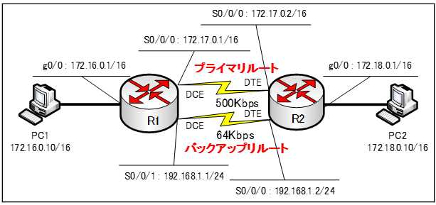
それでは、下図のように、
帯域幅が500Kbpsの Serial0/0/0 を経由するルートをプライマリルート
帯域幅が64Kbpsの Serial0/0/1 を経由するルートををバックアップルート
となるように、設定します。

帯域幅の大きい500Kbpsの回線を経由するルートを普段は、プライマリルートとして使用し、その回線に障害があった場合のみ帯域幅の狭い64Kbpsの回線を使うように設定していきます。
続きは、「RIPとフローティングスタティック(その2)」で解説します。
