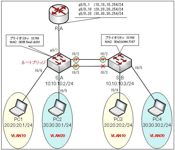
RSTP(Rapid PVST+)の収束の確認
それでは、RSTP(Rapid PVST+)がどれほど早く収束するのかを確認していきます。
事前に、S_BスイッチのCLIタブを表示して、TOPにチェックを入れておきます。
S_Bに挿してある「Fa0/2」ポートのケーブルを抜きます。
そして、素早く、S_Bで「show spanning-tree」コマンドを実行します。
S_B#show spanning-tree
●S_Bの「show spanning-tree」コマンドの出力
S_B#show spanning-tree
VLAN0001
  Spanning tree enabled protocol rstp
  Root ID    Priority    32769
             Address     0005.5EA2.DC98
             Cost        19
             Port        3(FastEthernet0/3)
             Hello Time  2 sec  Max Age 20 sec  Forward Delay 15 sec

  Bridge ID  Priority    32769  (priority 32768 sys-id-ext 1)
             Address     00E0.B044.7267
             Hello Time  2 sec  Max Age 20 sec  Forward Delay 15 sec
             Aging Time  20

Interface        Role Sts Cost      Prio.Nbr Type
---------------- ---- --- --------- -------- --------------------------------
Fa0/3            Root FWD 19        128.3    P2p

VLAN0010
  Spanning tree enabled protocol rstp
  Root ID    Priority    32778
             Address     0005.5EA2.DC98
             Cost        19
             Port        3(FastEthernet0/3)
             Hello Time  2 sec  Max Age 20 sec  Forward Delay 15 sec

  Bridge ID  Priority    32778  (priority 32768 sys-id-ext 10)
             Address     00E0.B044.7267
             Hello Time  2 sec  Max Age 20 sec  Forward Delay 15 sec
             Aging Time  20

Interface        Role Sts Cost      Prio.Nbr Type
---------------- ---- --- --------- -------- --------------------------------
Fa0/3            Root FWD 19        128.3    P2p
Fa0/4            Desg FWD 19        128.4    P2p

VLAN0020
  Spanning tree enabled protocol rstp
  Root ID    Priority    32788
             Address     0005.5EA2.DC98
             Cost        19
             Port        3(FastEthernet0/3)
             Hello Time  2 sec  Max Age 20 sec  Forward Delay 15 sec

  Bridge ID  Priority    32788  (priority 32768 sys-id-ext 20)
             Address     00E0.B044.7267
             Hello Time  2 sec  Max Age 20 sec  Forward Delay 15 sec
             Aging Time  20

Interface        Role Sts Cost      Prio.Nbr Type
---------------- ---- --- --------- -------- --------------------------------
Fa0/3            Root FWD 19        128.3    P2p
Fa0/5            Desg FWD 19        128.5    P2p
瞬く間に、「Fa0/3」がフォワーディングポートに切り替わります。
先ほど抜いたケーブルを、S_Bの「Fa0/2」ポートへ接続します。
R_Aルータの設定
引き続き、下図のネットワークをRSTP(Rapid PVST+)で構築していきます。
R_Aの設定を行い、VLAN間ルーティングが行えるようにします。

●R_AのVLANの設定
まず、R_AにVLANを作成して、インターフェイスにVLANを割り当てます。
Router(config)#hostname R_A
R_A(config)#int g0/0
R_A(config-if)#no shut
R_A(config-if)#int g0/0.1
R_A(config-subif)#encapsulation dot1q 1
R_A(config-subif)#ip address 10.10.10.254 255.255.255.0
R_A(config-if)#int g/0.10
R_A(config-subif)#encapsulation dot1q 10
R_A(config-subif)#ip address 20.20.20.254 255.255.255.0
R_A(config-if)#int g0/0.20
R_A(config-subif)#encapsulation dot1q 20
R_A(config-subif)#ip address 30.30.30.254 255.255.255.0
R_A(config-subif)#end
R_A#
ペースト用のコンフィグ
●R_Aのコンフィグ
hostname R_A
int g0/0
no shutdown
int g0/0.1
encapsulation dot1q 1
ip address 10.10.10.254 255.255.255.0
int g0/0.10
encapsulation dot1q 10
ip address 20.20.20.254 255.255.255.0
int g0/0.20
encapsulation dot1q 20
ip address 30.30.30.254 255.255.255.0
end
●R_Aの「show ip route」コマンドの出力
「show ip route」コマンドでルーティングテーブルを確認します。
R_A#show ip route
Codes: L - local, C - connected, S - static, R - RIP, M - mobile, B - BGP
       D - EIGRP, EX - EIGRP external, O - OSPF, IA - OSPF inter area
       N1 - OSPF NSSA external type 1, N2 - OSPF NSSA external type 2
       E1 - OSPF external type 1, E2 - OSPF external type 2, E - EGP
       i - IS-IS, L1 - IS-IS level-1, L2 - IS-IS level-2, ia - IS-IS inter area
       * - candidate default, U - per-user static route, o - ODR
       P - periodic downloaded static route

Gateway of last resort is not set

     10.0.0.0/8 is variably subnetted, 2 subnets, 2 masks
C       10.10.10.0/24 is directly connected, GigabitEthernet0/0
L       10.10.10.254/32 is directly connected, GigabitEthernet0/0
     20.0.0.0/8 is variably subnetted, 2 subnets, 2 masks
C       20.20.20.0/24 is directly connected, GigabitEthernet0/0.10
L       20.20.20.254/32 is directly connected, GigabitEthernet0/0.10
     30.0.0.0/8 is variably subnetted, 2 subnets, 2 masks
C       30.30.30.0/24 is directly connected, GigabitEthernet0/0.20
L       30.30.30.254/32 is directly connected, GigabitEthernet0/0.20
これで設定は、すべて完了です。
関連コンテンツ
演習ファイル(完了)のダウンロード
ネットワークの構成を Packet Tracer で一から設定していくのは大変かと思います。「ダウンロード」から演習を完了させたファイルのダウンロードができます。ファイルは、McAfee インターネットセキュリティでウイルスチェックをしておりますが、ダウンロードは自己責任でお願いいたします。
