ポリシーベースルーティング(設定ミス例)
先ほどの「ポリシーベースルーティング(送信元 その3)」の設定にコマンドを追加していきます。
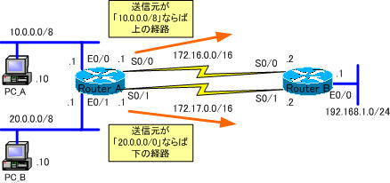
先ほど構築したネットワークは下のネットワークです。

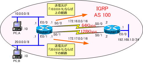
このネットワークをIGRPネットワークに変更します。

各ルータの設定は、以下のようになります。
●Router_Aの設定
!
version 12.0
service timestamps debug uptime
service timestamps log uptime
no service password-encryption
!
hostname Router_A
!
enable password cisco
!
ip subnet-zero
!
interface Ethernet0/0
 ip address 10.0.0.1 255.0.0.0
 ip policy route-map policy1
!
interface Serial0/0
 bandwidth 64
 ip address 172.16.0.1 255.255.0.0
 clockrate 64000
!
interface Ethernet0/1
 ip address 20.0.0.1 255.0.0.0
 ip policy route-map policy1
!
interface Serial0/1
 bandwidth 128
 ip address 172.17.0.1 255.255.0.0
 clockrate 128000
!
router igrp 100
 network 10.0.0.0
 network 20.0.0.0
 network 172.16.0.0
 network 172.17.0.0
!
ip classless
ip route 0.0.0.0 0.0.0.0 Serial0/1
!
access-list 100 permit ip 10.0.0.0 0.255.255.255 192.168.1.0 0.0.0.255
access-list 110 permit ip any 192.168.1.0 0.0.0.255
route-map policy1 permit 10
 match ip address 100
 set default interface Serial0/0
!
route-map policy1 permit 20
 match ip address 110
 set default interface Serial0/1
!
line con 0
 exec-timeout 0 0
 transport input none
line aux 0
line vty 0 4
 password cisco
 login
!
no scheduler allocate
end
●Router_Bの設定
!
version 12.0
service timestamps debug uptime
service timestamps log uptime
no service password-encryption
!
hostname Router_B
!
enable password cisco
!
ip subnet-zero
!
interface Ethernet0/0
 ip address 192.168.1.1 255.255.255.0
!
interface Serial0/0
 bandwidth 64
 ip address 172.16.0.2 255.255.0.0
!
interface Serial0/1
 bandwidth 128
 ip address 172.17.0.2 255.255.0.0
!
router igrp 100
 network 172.16.0.0
 network 172.17.0.0
 network 192.168.1.0
!
ip classless
!
line con 0
 exec-timeout 0 0
 transport input none
line aux 0
line vty 0 4
 password cisco
 login
!
no scheduler allocate
end
Router_Aのルーティングテーブルを確認します。
Gateway of last resort is not set

C    20.0.0.0/8 is directly connected, Ethernet0/1
C    172.17.0.0/16 is directly connected, Serial0/1
C    172.16.0.0/16 is directly connected, Serial0/0
C    10.0.0.0/8 is directly connected, Ethernet0/0
I    192.168.1.0/24 [100/80225] via 172.17.0.2, 00:00:03, Serial0/1
「192.168.1.0/24」への経路は、帯域幅が広い下(172.17.0.0/16)を通る経路がベストパスになっています。
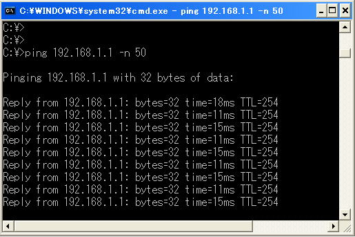
IPアドレス「10.0.0.10/8」のPC_AからPingを実行します。
Pingに「-n」オプションを指定して、50回、繰り返します。
C:¥>ping 192.168.1.1 -n 50

Router_Bでデバックを確認します。
ある程度、出力されたら、デバックをいったん止めておきます。
Router_B#no debug all
デバックを確認すると次のようになっています。
Router_B#debug ip packet
IP packet debugging is on
Router_B#
01:19:13: IP: s=10.0.0.10 (Serial0/1), d=192.168.1.1, len 60, rcvd 4
01:19:13: IP: s=192.168.1.1 (local), d=10.0.0.10 (Serial0/1), len 60, sending
01:19:14: IP: s=10.0.0.10 (Serial0/1), d=192.168.1.1, len 60, rcvd 4
01:19:14: IP: s=192.168.1.1 (local), d=10.0.0.10 (Serial0/1), len 60, sending
     ・
     ・
出力から分かるように、送信元IPアドレスが、「10.0.0.0/8」のパケットは下の経路を通っていることが確認できます。
ポリシーで、上の経路を通るように設定したにも、かかわらずです。
Router_Aでポリシーをデバックします。
Router_A#debug ip policy
デバックを確認すると次のようになっています。
Router_A#debug ip policy
Policy routing debugging is on
Router_A#
01:22:24: IP: s=10.0.0.10 (Ethernet0/0), d=192.168.1.1, len 60, policy match
01:22:24: IP: route map policy1, item 10, permit
01:22:24: IP: s=10.0.0.10 (Ethernet0/0), d=192.168.1.1 (Serial0/1), len 60,
 policy rejected -- normal forwarding
01:22:25: IP: s=10.0.0.10 (Ethernet0/0), d=10.255.255.255 (Ethernet0/0), len 237,
 policy rejected -- normal forwarding
     ・
     ・
黄色のマーク部分のメッセージから分かるように、ポリシーが拒絶されているのが確認できます。
ポリシールーティングを設定することにより、通常のルーティング動作を無効にしなければならないということが分かります。
次は、ポリシーベースルーティングの動作確認をするためのコマンドを紹介していきます。
続きは、次の「ポリシーベースルーティングの動作確認」で説明します。
