BGP(基本設定 iBGPとIGP)⑪
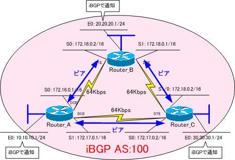
「BGP(基本設定 iBGPとIGP )⑩」では、下のネットワークをiBGPで構築しました。
iBGPで
・「10.10.10.0/24」の経路
・「20.20.20.0/24」の経路
・「30.30.30.0/24」の経路
のみを、やり取りするように「network」コマンドで指定したので、ルータ間の経路は、このままではやりとりされません。
つまり、前の設定のままでは、各ルータが扱う経路は、以下のようになっています。
・Router_Aでは、「172.18.0.0/24」の経路がありません。
・Router_Bでは、「172.17.0.0/24」の経路がありません。
・Router_Cでは、「172.16.0.0/24」の経路がありません。

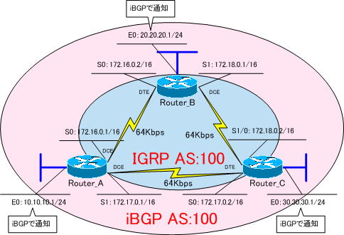
そこで、ルータ間の経路情報は、IGPで交換するようにします。
IGPには、IGRPを使います。

それでは、 「BGP(基本設定 iBGPとIGP )⑩」で設定した内容に、IGRPの設定を追加していきます。
各ルータの設定は、以下の通りです。
強制的にインターフェイスをUPさせるために、各ルータのE0インターフェイスで「no keepalive」コマンドを設定しておきます。
●Router_Aの設定
!
version 11.2
no service udp-small-servers
no service tcp-small-servers
!
hostname Router_A
!
enable password cisco
!
interface Ethernet0
 ip address 10.10.10.1 255.255.255.0
 no keepalive
!
interface Serial0
 ip address 172.16.0.1 255.255.0.0
 clockrate 64000
!
interface Serial1
 ip address 172.17.0.1 255.255.0.0
 clockrate 64000
!
router igrp 100
 network 172.16.0.0
 network 172.17.0.0
!
router bgp 100
 no synchronization
 network 10.10.10.0 mask 255.255.255.0
 neighbor 172.16.0.2 remote-as 100
 neighbor 172.17.0.2 remote-as 100
 no auto-summary
!
ip classless
!
line con 0
line aux 0
line vty 0 4
 password cisco
 login
!
end
●Router_Bの設定
!
version 11.2
no service udp-small-servers
no service tcp-small-servers
!
hostname Router_B
!
enable password cisco
!
interface Ethernet0
 ip address 20.20.20.1 255.255.255.0
 no keepalive
!
interface Serial0
 ip address 172.16.0.2 255.255.0.0
!
interface Serial1
 ip address 172.18.0.1 255.255.0.0
 clockrate 64000
!
router igrp 100
 network 172.16.0.0
 network 172.18.0.0
!
router bgp 100
 no synchronization
 network 20.20.20.0 mask 255.255.255.0
 neighbor 172.16.0.1 remote-as 100
 neighbor 172.18.0.2 remote-as 100
 no auto-summary
!
ip classless
!
line con 0
 exec-timeout 0 0
line aux 0
line vty 0 4
 password cisco
 login
!
end
●Router_Cの設定
!
version 11.2
no service udp-small-servers
no service tcp-small-servers
!
hostname Router_C
!
enable password cisco
!
interface Ethernet0
 ip address 30.30.30.1 255.255.255.0
 no keepalive
!
interface Serial0
 ip address 172.17.0.2 255.255.0.0
!
interface Serial1
 ip address 172.18.0.2 255.255.0.0
!
router igrp 100
 network 172.17.0.0
 network 172.18.0.0
!
router bgp 100
 no synchronization
 network 30.30.30.0 mask 255.255.255.0
 neighbor 172.17.0.1 remote-as 100
 neighbor 172.18.0.1 remote-as 100
 no auto-summary
!
ip classless
!
line con 0
 exec-timeout 0 0
line aux 0
line vty 0 4
 password cisco
 login
!
end
各ルータのルーティングテーブルを確認してみます。
●Router_Aのルーティングテーブル
Gateway of last resort is not set

     10.0.0.0/24 is subnetted, 1 subnets
C       10.10.10.0 is directly connected, Ethernet0
     20.0.0.0/24 is subnetted, 1 subnets
B       20.20.20.0 [200/0] via 172.16.0.2, 01:59:32
     30.0.0.0/24 is subnetted, 1 subnets
B       30.30.30.0 [200/0] via 172.17.0.2, 01:59:16
C    172.16.0.0/16 is directly connected, Serial0
C    172.17.0.0/16 is directly connected, Serial1
I    172.18.0.0/16 [100/10476] via 172.16.0.2, 00:00:01, Serial0
                   [100/10476] via 172.17.0.2, 00:00:19, Serial1
●Router_Bのルーティングテーブル
Gateway of last resort is not set

     10.0.0.0/24 is subnetted, 1 subnets
B       10.10.10.0 [200/0] via 172.16.0.1, 01:12:59
     20.0.0.0/24 is subnetted, 1 subnets
C       20.20.20.0 is directly connected, Ethernet0
     30.0.0.0/24 is subnetted, 1 subnets
B       30.30.30.0 [200/0] via 172.18.0.2, 01:15:37
C    172.16.0.0/16 is directly connected, Serial0
I    172.17.0.0/16 [100/10476] via 172.16.0.1, 00:00:46, Serial0
                   [100/10476] via 172.18.0.2, 00:00:56, Serial1
C    172.18.0.0/16 is directly connected, Serial1
●Router_Cのルーティングテーブル
Gateway of last resort is not set

     10.0.0.0/24 is subnetted, 1 subnets
B       10.10.10.0 [200/0] via 172.17.0.1, 01:13:27
     20.0.0.0/24 is subnetted, 1 subnets
B       20.20.20.0 [200/0] via 172.18.0.1, 01:16:06
     30.0.0.0/24 is subnetted, 1 subnets
C       30.30.30.0 is directly connected, Ethernet0
I    172.16.0.0/16 [100/10476] via 172.17.0.1, 00:01:14, Serial0
                   [100/10476] via 172.18.0.1, 00:00:04, Serial1
C    172.17.0.0/16 is directly connected, Serial0
C    172.18.0.0/16 is directly connected, Serial1
ルータ間の経路が、IGPで交換されているのが分かります。
ちなみに、
・Router_Aでは、「172.18.0.0/24」の経路がロードバランシングされています。
・Router_Bでは、「172.17.0.0/24」の経路がロードバランシングされています。
・Router_Cでは、「172.16.0.0/24」の経路がロードバランシングされています。
IGRPでは、RIPと同様に等コストロードバランシングが行われます。デフォルトで4つまでの経路で等コストバランシングが行えます。
これで、BGPの基本設定の説明は、終わりです。
