BGP(基本設定 iBGPの設定)⑥
・「BGP(基本設定 iBGPの設定)⑤」の続きです。
今度は、フルメッシュでiBGPを構成していきます。
配線を物理的にフルメッシュにしてピアを張る
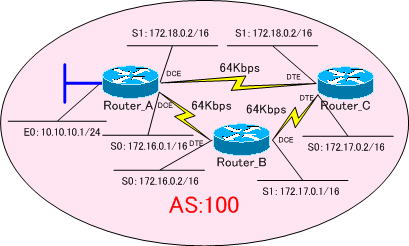
各ルータをフルメッシュでピアを張る為に、配線をフルメッシュとするネットワークで構築していきます。
使用するネットワークは、下図になります。

BGP同期は、無効にしておきます。BGP同期については、この後のコンテンツで紹介してゆきます。
ちなみに、BGP同期とは、『たとえBGPで経路情報を学習してもIGPで学習するまでは、その経路情報を有効にしない。』という機能のことです。
※BGP同期は、IOS12.2(8)以前のバージョンでは、デフォルトで有効になっています。
「no synchronization」コマンドで、BGP同期を無効にすることができます。
Router(config-router)#no synchronization
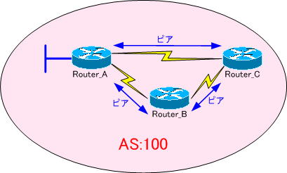
各ルータのピアを下図のように張ります。

「BGP(基本設定 iBGPの設定)⑤」で確認したように
iBGPでは、iBGPで受け取った経路情報を他のiBGPルータへ通知しません。
iBGPでは、ルーティングループを防ぐために、このようにBGPスプリットホライズンが働くようになっているからです。
その為、iBGPネットワークを構築する際は、1ポップで他の全ルータに接続できるように、フルメッシュでピアを張るのが基本的なアプローチになります。
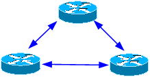
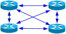
ただし、フルメッシュでピアを張ると、ルータの数が増えれば増えるほどピアの数が増大するという欠点があります。
| ルータが3台の場合 | ルータが4台の場合 |
 |  |
ピアの数が増えれば、ルータの設定が煩雑になりがちです。
そこで、ルートリフレクションを使ってピアの数を少なくするという方法もあります。ルートリフレクションについては、後ほどのコンテンツで紹介していきます。
各ルータの設定
それでは、各ルータをフルメッシュでピアを張り構成していきます。
※今回は、少し強引ですが、AS内のルートをiBGPでアドバタイズさせます。
強制的にインターフェイスをUPさせるために、Router_AのE0インターフェイスで「no keepalive」コマンドを設定しておきます。
●Router_Aの設定
!
version 11.2
no service udp-small-servers
no service tcp-small-servers
!
hostname Router_A
!
enable password cisco
!
interface Ethernet0
 ip address 10.10.10.1 255.255.255.0
 no keepalive
!
interface Serial0
 ip address 172.16.0.1 255.255.0.0
 clockrate 64000
!
interface Serial1
 ip address 172.18.0.1 255.255.0.0
 clockrate 64000
!
router bgp 100
 no synchronization
 network 10.10.10.0 mask 255.255.255.0
 network 172.16.0.0
 network 172.18.0.0
 neighbor 172.16.0.2 remote-as 100
 neighbor 172.18.0.2 remote-as 100
 no auto-summary
!
ip classless
!
line con 0
line aux 0
line vty 0 4
 password cisco
 login
!
end
●Router_Bの設定
!
version 11.2
no service udp-small-servers
no service tcp-small-servers
!
hostname Router_B
!
enable password cisco
!
interface Serial0
 ip address 172.16.0.2 255.255.0.0
!
interface Serial1
 ip address 172.17.0.1 255.255.0.0
 clockrate 64000
!
router bgp 100
 no synchronization
 network 172.16.0.0
 network 172.17.0.0
 neighbor 172.16.0.1 remote-as 100
 neighbor 172.17.0.2 remote-as 100
 no auto-summary
!
ip classless
!
line con 0
line aux 0
line vty 0 4
 password cisco
 login
!
end
●Router_Cの設定
!
version 11.2
no service udp-small-servers
no service tcp-small-servers
!
hostname Router_C
!
enable password cisco
!
interface Serial0
 ip address 172.17.0.2 255.255.0.0
!
interface Serial1
 ip address 172.18.0.2 255.255.0.0
!
router bgp 100
 no synchronization
 network 172.17.0.0
 network 172.18.0.0
 neighbor 172.17.0.1 remote-as 100
 neighbor 172.18.0.1 remote-as 100
 no auto-summary
!
ip classless
!
line con 0
 exec-timeout 0 0
line aux 0
line vty 0 4
 password cisco
 login
!
end
各ルータのルーティングテーブルを確認してみます。
●Router_Aのルーティングテーブル
Gateway of last resort is not set

     10.0.0.0/24 is subnetted, 1 subnets
C       10.10.10.0 is directly connected, Ethernet0
C    172.16.0.0/16 is directly connected, Serial0
B    172.17.0.0/16 [200/0] via 172.16.0.2, 00:01:27
C    172.18.0.0/16 is directly connected, Serial1
●Router_Bのルーティングテーブル
Gateway of last resort is not set

     10.0.0.0/24 is subnetted, 1 subnets
B       10.10.10.0 [200/0] via 172.16.0.1, 00:06:49
C    172.16.0.0/16 is directly connected, Serial0
C    172.17.0.0/16 is directly connected, Serial1
B    172.18.0.0/16 [200/0] via 172.16.0.1, 00:06:49
●Router_Cのルーティングテーブル
Gateway of last resort is not set

     10.0.0.0/24 is subnetted, 1 subnets
B       10.10.10.0 [200/0] via 172.18.0.1, 00:01:54
B    172.16.0.0/16 [200/0] via 172.17.0.1, 00:02:20
C    172.17.0.0/16 is directly connected, Serial0
C    172.18.0.0/16 is directly connected, Serial1
各ルータが全てのルートを学習していることが分かります。
次の「BGP(基本設定 iBGPの設定)⑦」では、ループバックアドレスを使ったピアを張り方を紹介します。
