ルートフィルタ設定(標準アクセスリスト)
ルートフィルタの設定を行います。ここでは、標準アクセスリストを使ってフィルタを作成し、インターフェイスの受信時にフィルタを仕掛けてみます。
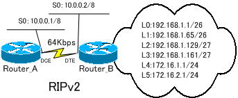
まずは、フィルタを作成しないで下のRIPv2によるネットワークを構築します。

※ルート集約しないように「no auto-summary」コマンドを使用します。
各ルータのルーティングの設定は、以下のようになります。
●Router_A
Router_A(config)#router rip
Router_A(config-router)#version 2
Router_A(config-router)#network 10.0.0.0
Router_A(config-router)#no auto-summary
●Router_B
Router_B(config)#router rip
Router_B(config-router)#version 2
Router_B(config-router)#network 10.0.0.0
Router_B(config-router)#network 172.16.0.0
Router_B(config-router)#network 192.168.1.0
Router_B(config-router)#no auto-summary
●Router_Aの設定
!
version 12.3
service timestamps debug datetime msec
service timestamps log datetime msec
no service password-encryption
!
hostname Router_A
!
boot-start-marker
boot-end-marker
!
enable password cisco
!
no aaa new-model
ip subnet-zero
!
ip cef
!
interface FastEthernet0
 no ip address
 shutdown
 speed auto
!
interface Serial0
 ip address 10.0.0.1 255.0.0.0
 clockrate 64000
 no fair-queue
!
router rip
 version 2
 network 10.0.0.0
 no auto-summary
!
ip classless
no ip http server
!
line con 0
line aux 0
line vty 0 4
 password cisco
 login
!
end
●Router_Bの設定
!
version 12.1
service timestamps debug uptime
service timestamps log uptime
no service password-encryption
!
hostname Router_B
!
enable password cisco
!
memory-size iomem 25
ip subnet-zero
!
interface Loopback0
 ip address 192.168.1.1 255.255.255.192
!
interface Loopback1
 ip address 192.168.1.65 255.255.255.192
!
interface Loopback2
 ip address 192.168.1.129 255.255.255.224
!
interface Loopback3
 ip address 192.168.1.161 255.255.255.224
!
interface Loopback4
 ip address 172.16.1.1 255.255.255.0
!
interface Loopback5
 ip address 172.16.2.1 255.255.255.0
!
interface Serial0
 ip address 10.0.0.2 255.0.0.0
 no fair-queue
!
interface Serial1
 no ip address
 shutdown
!
interface FastEthernet0
 no ip address
 shutdown
 speed auto
!
router rip
 version 2
 network 10.0.0.0
 network 172.16.0.0
 network 192.168.1.0
 no auto-summary
!
ip classless
no ip http server
!
line con 0
 transport input none
line aux 0
line vty 0 4
 password cisco
 login
!
no scheduler allocate
end
Router_Aのルーティングテーブルを表示します。
●Router_Aのルーティングテーブル
Gateway of last resort is not set

     172.16.0.0/24 is subnetted, 2 subnets
R       172.16.1.0 [120/1] via 10.1.12.2, 00:00:25, Serial0
R       172.16.2.0 [120/1] via 10.1.12.2, 00:00:25, Serial0
C    10.0.0.0/8 is directly connected, Serial0
     192.168.1.0/24 is variably subnetted, 4 subnets, 2 masks
R       192.168.1.64/26 [120/1] via 10.1.12.2, 00:00:25, Serial0
R       192.168.1.0/26 [120/1] via 10.1.12.2, 00:00:25, Serial0
R       192.168.1.160/27 [120/1] via 10.1.12.2, 00:00:25, Serial0
R       192.168.1.128/27 [120/1] via 10.1.12.2, 00:00:26, Serial0
すべてのルートが表示されています。
フィルタの作成と適用
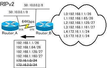
Router_Bから送信されるルート情報のうち、Router_Aで、192.168.1.0/26、192.168.1.64/26、192.168.1.128/27、192.168.1.160/27のルートのみを受信するようにします。
Router_Aで標準アクセスリストを使ってフィルタを作成し、S0の『IN』にフィルタを配置します。

●フィルタの作成
Router_A(config)#access-list 1 permit 192.168.1.0 0.0.0.255
4つのルートは、先頭の「192.168.1.」が共通です。ワイルドカードマスクを「0.0.0.255」と指定すると4つのルートを許可するようになります。
●フィルタの配置
フィルタの配置は、ルーティングプロセスで指定します。
Router_A(config)#router rip
Router_A(config-router)#distribute-list 1 in s0
Router_Aで、標準アクセスリストによるフィルタをS0の「IN」に適用することにより、Router_Bから送られてくる経路のうち、192.168.1.0/26、192.168.1.64/26、192.168.1.128/27、192.168.1.160/27の4つのルートのみを受信するようになります。
Router_Aのルーティングテーブルを表示してみます。
●Router_Aのルーティングテーブル
Gateway of last resort is not set

C    10.0.0.0/8 is directly connected, Serial0
     192.168.1.0/24 is variably subnetted, 4 subnets, 2 masks
R       192.168.1.64/26 [120/1] via 10.1.12.2, 00:00:04, Serial0
R       192.168.1.0/26 [120/1] via 10.1.12.2, 00:00:04, Serial0
R       192.168.1.160/27 [120/1] via 10.1.12.2, 00:00:04, Serial0
R       192.168.1.128/27 [120/1] via 10.1.12.2, 00:00:04, Serial0
R 172.16.1.0 [120/1] via 10.1.12.2, 00:00:05, Serial0
R 172.16.2.0 [120/1] via 10.1.12.2, 00:00:05, Serial0
のルートを受信しなくなりました。これは、Router_A側で、「172.16.1.0」「172.16.2.0」のルートをフィルタしたからです。
次は、プレフィクスリストを使用して、インターフェイスの送信時にプレフィクスリストを適用してルートフィルタを検証してみます。続きは、「ルートフィルタ設定(プレフィクスリスト)」で紹介します。
