BGPルートの生成(networkコマンド)
BGPでルートを生成するには、静的な方法、動的な方法のどちらかで行うようになります。
静的な方法では、ルーティングプロトコルではなく、手動でBGP経路を作成します。動的な方法では、RIP、IGRP、OSPFなどのIGPから経路情報をBGPへ再配送します。
BGPでは、以下の3通りの方法で、ルートを生成します。
- networkコマンド
- aggregate-addressコマンド(経路集約)
- AS内のIGPから再配送
BGPルートを生成するのに、静的、動的のどちらの方法が良いのかは、BGPへ再配送する経路の数が1つの目安になります。
数本の経路をBGPへ注入するのであれば、静的な方法が楽で良い方法ですし、たくさんの経路をBGPへ注入するのであれば、IGPから再配送する動的な方法が楽です。
IGPから再配送する場合には、他にも考慮しなければならないことがあります。
それは、IGP側で不安定な状態が続くとBGPプロセスへも影響するということです。
以上のようなことを考慮して、BGPでは、ルートを生成してゆきます。
ここでは、「network」コマンドを使った静的にBGPルートの生成する方法を説明してゆきます。
・動的にルートを生成する方法については、「BGPルートの生成(IGPから再配送 その1)」で紹介します。
・集約した経路を作成する方法については、「BGPルートの生成(経路集約 その1)」で紹介します。
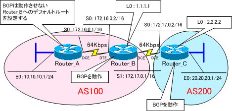
使用するネットワークは、下図になります。このネットワークを使用して、BGPへ静的再配送を行います。

●ネットワーク構成図の補足
Router_A ・・・ BGPは動作させません。
Router_B ・・・ BGPを動作させる。
Router_C ・・・ BGPを動作させる。
Router_B~Router_C間は、BGPでルーティングを行います。所属するASが異なりますから、eBGPでルーティングが行われることになります。また、ピアを張るにお互いのループバックアドレスを使用しますので、eBGPマルチホップの設定が必要になります。
Router_B~Router_C間は、ループバックIPアドレスへは静的ルートで到達させます。
Router_A ・・・ Router_Bへのデフォルトルートを設定します。
静的にBGPルートを生成するには
静的にBGPルートを生成するには「network」コマンドを使用します。このコマンドは、ルート情報を生成するコマンドで、指定したルート情報をBGPテーブルに載せてベストパスにします。
一度に1つのBGPルートしか生成できませんが、複数生成する場合は、自律システム内のネットワークを列挙するだけなので、設定は単純です。
構文は以下のようになります。
Router(config-router)#network [ネットワークアドレス] mask [サブネットマスク]
それでは、ネットワークの構成とコマンドが理解できたところで、各ルータの設定を行ってゆきます。
各ルータのルーティングの設定
●Router_A
Router_A(config)#ip route 0.0.0.0 0.0.0.0 172.16.0.2
●Router_B
Router_B(config)#router bgp 100
Router_B(config-router)#no synchronization
Router_B(config-router)#network 10.10.10.0 mask 255.255.255.0
Router_B(config-router)#network 172.16.0.0 mask 255.255.0.0
Router_Bに直接接続されていない「10.10.10.0./24」をBGPで指定しています。

この「network 10.10.10.0 mask 255.255.255.0」という指定の仕方は、RIPは、IGRPなどのディスタンスベクタルーティングプロトコルの指定の仕方をイメージすると馴染みにくいと感じるかもしれません。
●Router_C
Router_C(config)#router bgp 200
Router_C(config-router)#no synchronization
Router_C(config-router)#network 20.20.20.0 mask 255.255.255.0
Router_C(config-router)#neighbor 1.1.1.1 remote-as 100
各ルータの設定は、以下のようになります。
強制的にインターフェイスをUPさせるために、Router_A、Router_CのE0インターフェイスで「no keepalive」コマンドを設定しておきます。
●Router_Aの設定
!
version 11.2
no service udp-small-servers
no service tcp-small-servers
!
hostname Router_A
!
enable password cisco
!
interface Ethernet0
 ip address 10.10.10.1 255.255.255.0
 no keepalive
!
interface Serial0
 ip address 172.16.0.1 255.255.0.0
 clockrate 64000
!
ip classless
ip route 0.0.0.0 0.0.0.0 172.16.0.2
!
line con 0
line aux 0
line vty 0 4
 password cisco
 login
!
end
●Router_Bの設定
!
version 11.2
no service udp-small-servers
no service tcp-small-servers
!
hostname Router_B
!
enable password cisco
!
interface Loopback0
 ip address 1.1.1.1 255.255.255.255
!
interface Serial0
 ip address 172.16.0.2 255.255.0.0
!
interface Serial1
 ip address 172.17.0.1 255.255.0.0
 clockrate 64000
!
router bgp 100
 no synchronization
 network 10.10.10.0 mask 255.255.255.0
 network 172.16.0.0
 neighbor 2.2.2.2 remote-as 200
 neighbor 2.2.2.2 ebgp-multihop 255
 neighbor 2.2.2.2 update-source Loopback0
 no auto-summary
!
ip classless
ip route 2.2.2.2 255.255.255.255 172.17.0.2
ip route 10.10.10.0 255.255.255.0 172.16.0.1
!
line con 0
 exec-timeout 0 0
line aux 0
line vty 0 4
 password cisco
 login
!
end
●Router_Cの設定
!
version 11.2
no service udp-small-servers
no service tcp-small-servers
!
hostname Router_C
!
enable password cisco
!
interface Loopback0
 ip address 2.2.2.2 255.255.255.255
!
interface Ethernet0
 ip address 20.20.20.1 255.255.255.0
 no keepalive
!
interface Serial0
 ip address 172.17.0.2 255.255.0.0
!
interface Serial1
 ip address 172.18.0.1 255.255.0.0
 clockrate 64000
!
router bgp 200
 no synchronization
 network 20.20.20.0 mask 255.255.255.0
 neighbor 1.1.1.1 remote-as 100
 neighbor 1.1.1.1 ebgp-multihop 255
 neighbor 1.1.1.1 update-source Loopback0
 no auto-summary
!
ip classless
ip route 1.1.1.1 255.255.255.255 172.17.0.1
!
line con 0
 exec-timeout 0 0
line aux 0
line vty 0 4
 password cisco
 login
!
end
Router_Bのルーティングテーブルを確認してみます。
Gateway of last resort is not set

     1.0.0.0/32 is subnetted, 1 subnets
C       1.1.1.1 is directly connected, Loopback0
     2.0.0.0/32 is subnetted, 1 subnets
S       2.2.2.2 [1/0] via 172.17.0.2
     10.0.0.0/24 is subnetted, 1 subnets
S       10.10.10.0 [1/0] via 172.16.0.1
     20.0.0.0/24 is subnetted, 1 subnets
B       20.20.20.0 [20/0] via 2.2.2.2, 00:03:44
C    172.16.0.0/16 is directly connected, Serial0
C    172.17.0.0/16 is directly connected, Serial1
Router_Cから「20.20.20.0/24」の経路をBGPで学習していることが確認できます。
Router_Cのルーティングテーブルを確認してみます。
Gateway of last resort is not set

     1.0.0.0/32 is subnetted, 1 subnets
S       1.1.1.1 [1/0] via 172.17.0.1
     2.0.0.0/32 is subnetted, 1 subnets
C       2.2.2.2 is directly connected, Loopback0
     10.0.0.0/24 is subnetted, 1 subnets
B       10.10.10.0 [20/0] via 1.1.1.1, 00:01:15
     20.0.0.0/24 is subnetted, 1 subnets
C       20.20.20.0 is directly connected, Ethernet0
B    172.16.0.0/16 [20/0] via 1.1.1.1, 00:01:15
C    172.17.0.0/16 is directly connected, Serial0
Router_Bから「10.10.10.0/24」、「172.16.0.0/16」の経路をBGPで学習していることが確認できます。
次の「BGPルートの生成(IGPから再配送 その1)」では、IGPを使ってBGPへ経路を注入する方法を紹介します。
