BGP(eBGPマルチホップ その2)
「BGP(eBGPマルチホップ その1)」の続きです。
eBGPマルチホップの設定方法は、 「BGP(eBGPマルチホップ その1)」を参考にしてみて下さい。
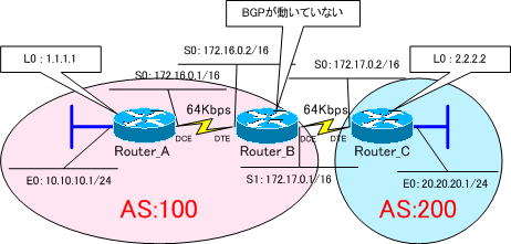
下図のネットワークをeBGPマルチホップで構築します。
Router_Bでは、BGPを動作させません。
それでは、各ルータを設定していきます。

各ルータの設定は、以下のようになります。
強制的にインターフェイスをUPさせるために、Router_AのE0インターフェイスで「no keepalive」コマンドを設定しておきます。
●Router_Aの設定
!
version 11.2
no service udp-small-servers
no service tcp-small-servers
!
hostname Router_A
!
enable password cisco
!
interface Loopback0
 ip address 1.1.1.1 255.255.255.255
!
interface Ethernet0
 ip address 10.10.10.1 255.255.255.0
 no keepalive
!
interface Serial0
 ip address 172.16.0.1 255.255.0.0
 clockrate 64000
!
router bgp 100
 no synchronization
 network 10.10.10.0 mask 255.255.255.0
 neighbor 2.2.2.2 remote-as 200
 neighbor 2.2.2.2 ebgp-multihop 255
 neighbor 2.2.2.2 update-source Loopback0
 no auto-summary
!
ip classless
ip route 2.2.2.2 255.255.255.255 172.16.0.2
ip route 172.17.0.0 255.255.0.0 172.16.0.2
!
line con 0
line aux 0
line vty 0 4
 password cisco
 login
!
end
●Router_Bの設定
!
version 11.2
no service udp-small-servers
no service tcp-small-servers
!
hostname Router_B
!
enable password cisco
!
interface Serial0
 ip address 172.16.0.2 255.255.0.0
!
interface Serial1
 ip address 172.17.0.1 255.255.0.0
 clockrate 64000
!
ip classless
ip route 1.1.1.1 255.255.255.255 172.16.0.1
ip route 2.2.2.2 255.255.255.255 172.17.0.2
!
line con 0
 exec-timeout 0 0
line aux 0
line vty 0 4
 password cisco
 login
!
end
●Router_Cの設定
!
version 11.2
no service udp-small-servers
no service tcp-small-servers
!
hostname Router_C
!
enable password cisco
!
interface Loopback0
 ip address 2.2.2.2 255.255.255.255
!
interface Ethernet0
 ip address 20.20.20.1 255.255.255.0
 no keepalive
!
interface Serial0
 ip address 172.17.0.2 255.255.0.0
!
interface Serial1
 ip address 172.18.0.1 255.255.0.0
 clockrate 64000
!
router bgp 200
 no synchronization
 network 20.20.20.0 mask 255.255.255.0
 neighbor 1.1.1.1 remote-as 100
 neighbor 1.1.1.1 ebgp-multihop 255
 neighbor 1.1.1.1 update-source Loopback0
 no auto-summary
!
ip classless
ip route 1.1.1.1 255.255.255.255 172.17.0.1
ip route 172.16.0.0 255.255.0.0 172.17.0.1
!
line con 0
 exec-timeout 0 0
line aux 0
line vty 0 4
 password cisco
 login
!
end
Router_AのBGPテーブルを確認してみます。
Router_A#show ip bgp
BGP table version is 3, local router ID is 1.1.1.1
Status codes: s suppressed, d damped, h history, * valid, > best, i - internal
Origin codes: i - IGP, e - EGP, ? - incomplete

   Network          Next Hop          Metric LocPrf Weight Path
*> 10.10.10.0/24    0.0.0.0                0         32768 i
*> 20.20.20.0/24    2.2.2.2                0             0 200 i
「20.20.20.0/24」の経路が、「>」よりベストパスになっているのが確認できます。
Router_CのBGPテーブルを確認してみます。
Router_C#show ip bgp
BGP table version is 6, local router ID is 2.2.2.2
Status codes: s suppressed, d damped, h history, * valid, > best, i - internal
Origin codes: i - IGP, e - EGP, ? - incomplete

   Network          Next Hop          Metric LocPrf Weight Path
*> 10.10.10.0/24    1.1.1.1                0             0 100 i
*> 20.20.20.0/24    0.0.0.0                0         32768 i
「10.10.10.0/24」の経路が、「>」よりベストパスになっているのが確認できます。
Router_Aのルーティングテーブルを確認してみると
Gateway of last resort is not set

     1.0.0.0/32 is subnetted, 1 subnets
C       1.1.1.1 is directly connected, Loopback0
     2.0.0.0/32 is subnetted, 1 subnets
S       2.2.2.2 [1/0] via 172.16.0.2
     10.0.0.0/24 is subnetted, 1 subnets
C       10.10.10.0 is directly connected, Ethernet0
     20.0.0.0/24 is subnetted, 1 subnets
B       20.20.20.0 [20/0] via 2.2.2.2, 00:03:55
C    172.16.0.0/16 is directly connected, Serial0
S    172.17.0.0/16 [1/0] via 172.16.0.2
「20.20.20.0/24」の経路があります。
Router_Cのルーティングテーブルを確認してみると
Gateway of last resort is not set

     1.0.0.0/32 is subnetted, 1 subnets
S       1.1.1.1 [1/0] via 172.17.0.1
     2.0.0.0/32 is subnetted, 1 subnets
C       2.2.2.2 is directly connected, Loopback0
     10.0.0.0/24 is subnetted, 1 subnets
B       10.10.10.0 [20/0] via 1.1.1.1, 00:02:53
     20.0.0.0/24 is subnetted, 1 subnets
C       20.20.20.0 is directly connected, Ethernet0
S    172.16.0.0/16 [1/0] via 172.17.0.1
C    172.17.0.0/16 is directly connected, Serial0
「10.10.10.0/24」の経路があります。
次の「BGPルートの生成(networkコマンド)」では、このネットワークを使用して、再び、eBGPマルチホップで構築しますが、今度は、IGPをBGPへ再配送させることで、ルーティングを可能にさせます。
