What is OSPF
Features of OSPF
OSPF is a link-state routing protocol standardized by the IETF. Unlike EIGRP, which was originally developed by Cisco, routing is possible between multi-vendor routers other than Cisco routers. One of the major features of OSPF is the concept of areas.
Area concept
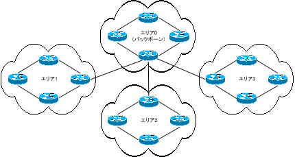
An OSPF network allows you to build your network in a hierarchical structure by configuring a small network as one area and connecting multiple areas to area 0 (backbone). The area-based design approach of group management keeps network changes within the area and improves performance. As a result, convergence time is reduced.
Each area must be connected to area 0 (backbone). An OSPF network that connects multiple areas is called multi-area OSPF. The CCNA test covers single-area OSPF, which consists of area 0 (backbone) only.
OSPF can build large-scale networks compared to distance vector routing protocols such as RIP and IGRP.
However, as the scale of the network grows, problems emerge.
To begin with, OSPF is a routing protocol with a very high load on routers that uses Dijkstra’s algorithm in its calculations to find the shortest path. It consumes a lot of router CPU and memory resources. As the scale of the network increases, the load on routers increases.
Also, as the scale of the network increases, the possibility of failures and network changes increases, so frequent recalculation of SPF (shortest path priority) becomes necessary.
Furthermore, since the number of routers will increase, the number of LSAs exchanged between routers to build the topology database will also increase.
Therefore, in OSPF, when the scale of the network becomes large, the network is divided into multiple areas and a multi-area network is constructed as shown in the figure above.
An OSPF network allows you to build your network in a hierarchical structure by configuring a small network as one area and connecting multiple areas to area 0 (backbone). In this way, one network is divided into multiple areas, and the method of dividing it into intra-area and inter-area routing is called “hierarchical routing.”
This area-defining design approach allows us to segment the reach of LSAs, keeping network changes within the area and improving performance.
As explained above, OSPF has a rule that each area must be connected to area 0 (backbone area). Anything other than area 0 must be connected to this backbone area. There is a rule that single-area OSPF, which is the scope of CCNA testing, must be configured with area 0 only.
router type
OSPF routers are called by three types of names according to their role. Depending on its role, the types of advertisements sent and received and the OSPF tree information will differ.
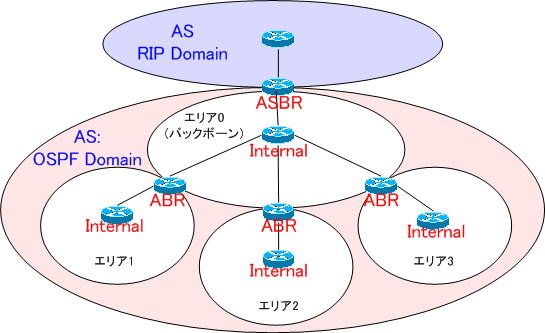
●Internal : Internal Router
A router whose interfaces connect only to routers within the same area. No contact with other areas.
●ABR: Area Border Router
A router that has interfaces connected to other areas.
● ASBR: AS Boundary Router
A router with interfaces that connect to other ASes or networks using routing protocols other than OSPF.
LSA
In single-area OSPF, you don’t have to worry too much about the types of LSAs in particular, but in multi-area OSPF, you exchange a great many types of LSAs. You need to know what type of LSA you have.
Below are some of the types of LSAs available. There are many types of LSA types, and the name of the name may be different in the manual and each vendor’s manual. Multi-area OSPF requires an understanding of LSA types.
| type | name | generate router | range | explanation |
| 1 | Router-LSA | All OSPF routers | within the area | Information about links in the area. Generated by all routers, notification range is limited to area. |
| 2 | Network LSA | DR | within the area | Generated by the designated router (DR) on the multi-access network. Notify the DR’s IP address, router ID, list of router IDs on the same multi-access network, and subnet mask. The notification range is limited within the same area. |
| 3 | Network Summary LSA | ABRMore | within the area | Notify route information to networks between areas. It is generated by an area border router (ABR) and is scoped to an area only. A default route and an aggregate route can be notified. |
| 4 | ASBR Summary LSA | ABRMore | within the area | Notifies the router ID of the ASBR (AS border router) connected to the non-OSPF network and the metric information to the ASBR. Generated by ABR, notification range is limited to area. |
| 5 | AS External LSA | ASBR | Entire OSPF domain excluding stub areas | Advertise routing information to non-OSPF networks. It is generated by an ASBR and advertised throughout the OSPF domain, excluding stub areas. The metric of AS external routes can be advertised as fixed or advertised in increments. |
| 7 | NSSA External LSA | ASBRs in NSSAs | NSSA | Generated by ASBRs within the NSSA area. Type 7 LSAs are only flooded within the NSSA area. Therefore, the ABR within the NSSA converts LSA type 7 to LSA type 5 and advertises it within the OSPF domain. |
*LSA type 6 also exists, but it is flooded by multicast OSPF routers. We omit it here.
OSPF (route learning process)
When OSPF is set on a router, Hello packets are sent from all interfaces participating in the OSPF process, neighboring routers are detected, and registered in the neighbor table.
Once the adjacency is formed, link information such as IP address, subnet mask, metric, etc. called LSA (Link State Advertisement) is sent to neighboring routers by multicast.
OSPF routers collect this LSA and register it in their link state database. After learning all LSAs, Dijkstra’s SPF (Shortest Path First algorithm) is run to compute the shortest path for each destination network.
When calculating this SPF, the cost, which is calculated by “10 8 /bandwidth”, is used. The obtained shortest path is registered in the routing table.
| bandwidth | cost |
| 56kbps | 1785 |
| T1 1.544Mbps | 64 |
| 10Mbps | Ten |
| 100Mbps | 1 |
When the OSPF learning process is executed and the routing table is completed, Hello packets will be sent using the multicast address “224.0.0.5” in order to maintain the adjacency relationship.
The interval for sending this Hello packet varies depending on the type of network.
●Broadcast network
・Default Hello interval ・・・ 10 seconds
・Default Dead interval ・・・ 40 seconds
●NBMA network
・Default Hello Interval ・・・ 30 seconds
・Default Dead Interval ・・・ 120 seconds
By default, the dead interval is set to a value four times the hello interval value. The dead interval is the amount of time an OSPF router considers dead. A Hello packet is considered invalid if it is not received four times.
The Hello interval and Dead interval settings can be freely set by the administrator, but they must match between neighboring routers. In EIGRP, different values were fine, but in OSPF, it is necessary to match them, so be careful.
● Hello interval / Dead interval setting
To set the Hello interval and Dead interval, execute the command below in interface configuration mode.
Router(config-if)#ip ospf hello-interval {seconds}
Router(config-if)#ip ospf dead-interval {seconds}
Since OSPF is a link-state routing protocol, unlike distance vector routing protocols such as RIP and IGRP, it does not perform frequent routing updates, but it sends LSA packets every 30 minutes to maintain information. Remember that LSAs are exchanged periodically even after convergence.
OSPF (Selection of DR/BDR)
OSPF uses neighbor relationships to share routing information. This proximity is called adjacency. When adjacencies are established on the OSPF network to which they are attached, they exchange link-state information.
For example, if you have 5 routers as shown in the diagram below, you will need 10 adjacencies.
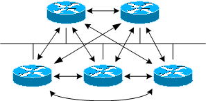
If you have n routers, you need n*(n-1)/2 adjacencies.
So if you have 10 routers, you will need 45 adjacencies. In this case, the more routers you have, the more adjacencies you need.
Establishing adjacencies and exchanging link-state information with all neighboring routers can add a lot of overhead.
Election of DR, BDR
Therefore, OSPF automatically recognizes the following three types of networks and selects DR and BDR.
* DR (designated router): It is called a “designated router”.
*BDR (backup designated router): It is called a “backup designated router
. “
- Broadcast multi-access: Ethernet, etc.
- Point-to-point networks: PPP, HDLC
- Non-Broadcast Multi-Access (NBMA): Frame Relay, etc.
In broadcast multi-access and non-broadcast multi-access, election of DR and BDR is performed. In point-to-point network, election of DR and BDR is not performed.
The DR forms adjacencies with all other routers in the broadcast segment, and other routers in the segment send their link state information to the DR. If the DR fails, the BDR will take over the role of the DR.
Election of DR, BDR reduces the overhead of exchanging link state information and saves bandwidth.
By the way, by electing DR and BDR, in a five router environment, DR and BDR will receive LSA as shown in the figure below.
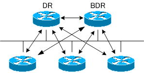
In Ethernet, one DR and one BDR are elected. The criteria for selecting DR and BDR are determined by PRIORITY and ROUTERID.
DR election is determined by the following rules: However, DR and BDR are not always elected as expected. The timing of powering on the router also plays a role. If another router has already been elected as the DR before the OSPF process starts up, the router started (added) later will not be the DR, no matter how high the ROUTERID and priority are. Can’t become DR until is down.
DR election rules
1. A router with the highest priority is elected in the order of DR and BDR.
PRIORITY=0 to 255, the higher the number, the higher the priority. If the value is 0, it will not be elected as DR.
2. If the priorities are the same, the routers with the largest ROUTERID are selected first, followed by the DR and then the BDR.
If an IP address is set for the loopback interface, the IP address assigned to the loopback interface will be the ROUTERID. Loopback interfaces take precedence over physical interfaces.
A loopback interface is a virtual interface that never goes down unless the router itself goes down. In an OSPF network, set this if you want to make it appear that there is always an active interface to ensure stability.
The ROUTERID is the highest numbered IP address of the active physical interface. For example, if “192.168.1.1” and “192.168.1.2” are set for the physical interfaces of the router, “192.168.1.2” has a higher number, so the ROUTERID will be “192.168.1.2”.
If there are multiple active interfaces, the ROUTERID will be the highest IP address assigned to the interface of the device itself.
In other words, regarding the selection of DR and BDR,
- PRIORITY
- IP address of the loopback interface
- IP address of the physical interface
If you pay attention to the order of , you can see which router is elected as DR and BDR.
Thus, once the DR and BDR are determined, the DR sends LSA updates using the multicast address “224.0.0.5”. Routers other than DR and BDR will send LSA updates to DR and BDR using multicast address “224.0.0.6”.

