TFTP server
TFTP server
TFTPD64
There are some TFTP software that can be used for free, but “TFTPD64” is a TFTP server free software that can be easily operated on Windows 10 with a GUI.
It can be used simply by setting the “current directory” of the public directory and “server interfaces” of the connection interface.
You can download it from the following site.
https://pjo2.github.io/tftpd64/
For Cisco equipment
-Upload config file
I will try uploading and downloading in the following environment.
| TFTP server IP address | 192.168.1.1 |
| Switch IP address | 192.168.1.10 |
| filename to upload | running-config |
First, set an IP address on your router. Don’t forget “no shutdown”. The port must be up.
| Router(config-if)#ip address 192.168.1.10 255.255.255.0 Router(config-if)#no shutdown |
PING the TFTP server to check whether communication with the TFTP server is possible.
| Router#ping 192.168.1.1 Type escape sequence to abort. Sending 5, 100-byte ICMP Echos to 192.168.1.1, timeout is 2 seconds: !!!!! Success rate is 100 percent (5/5), round-trip min /avg/max = 1/1/4ms |
Upload “running-config” to TFTP server.
| Router#copy running-config tftp Address or name of remote host []? 192.168.1.1 ← Enter TFTP server address Destination filename [router-confg]? ← Press <Enter> to accept the default name !! 926 bytes copied in 2.132 secs (463 bytes/sec) |
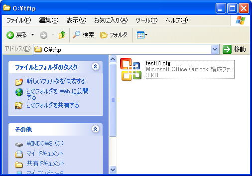
If the upload is successful, “runnnig-config” will be saved in the folder specified in TFTP.

For Allied Telesis equipment
-Upload config file
Try uploading in the following environment.
| TFTP server IP address | 192.168.1.1 |
| Switch IP address | 192.168.1.10 |
| filename to upload | test01.cfg |
First, create a config file to upload. Here, create “test01.cfg”.
| Manager > create config=test01.cfg Info (149003): Operation successful. |
Enable the switch’s IP module and assign an IP address to the VLAN interface.
| Manager > enable ip Info (105287): IP module has been enabled. Manager > add ip interface=vlan1 ipaddress=192.168.1.10 mask=255.255.255.0 Info (105275): interface successfully added. |
Now, all ports on the switch belong to VLAN1 and can be accessed with the IP address “192.168.1.10”.
PING the TFTP server to check whether communication with the TFTP server is possible.
| Manager > ping 192.168.1.1 Echo reply 1 from 192.168.1.1 time delay 0 ms Echo reply 2 from 192.168.1.1 time delay 0 ms Echo reply 3 from 192.168.1.1 time delay 0 ms Echo reply 4 from 192.168.1.1 time delay 0 ms Echo reply 5 from 192.168.1.1 time delay 0 ms |
Upload files. (switch → TFTP server)
Use the UPLOAD command.
UPLOAD [METHOD={TFTP|ZMODEM}] [FILE= filename ] [SERVER={ hostname | ipadd }] [ASYN= asyn-number ]
filename : File name
hostname : Host name
ipadd : IP address
asyn-number : Asynchronous port number (0~)
| Manager > upload file=test01.cfg server=192.168.1.1 Manager > Info (148270): File transfer successfully completed. |
If the file upload was successful, let’s check if it is saved properly on the PC side.


